
Ultra wideband communications systems

a communication system and wideband technology, applied in multi-frequency code systems, digital transmission, duplex signal operation, etc., to achieve the effects of reducing inter-packet delays, reducing turnaround time, and low cos

Inactive Publication Date: 2008-06-26
ARTIMI
View PDF7 Cites 12 Cited by
  • Summary
  • Abstract
  • Description
  • Claims
  • Application Information

AI Technical Summary

Benefits of technology

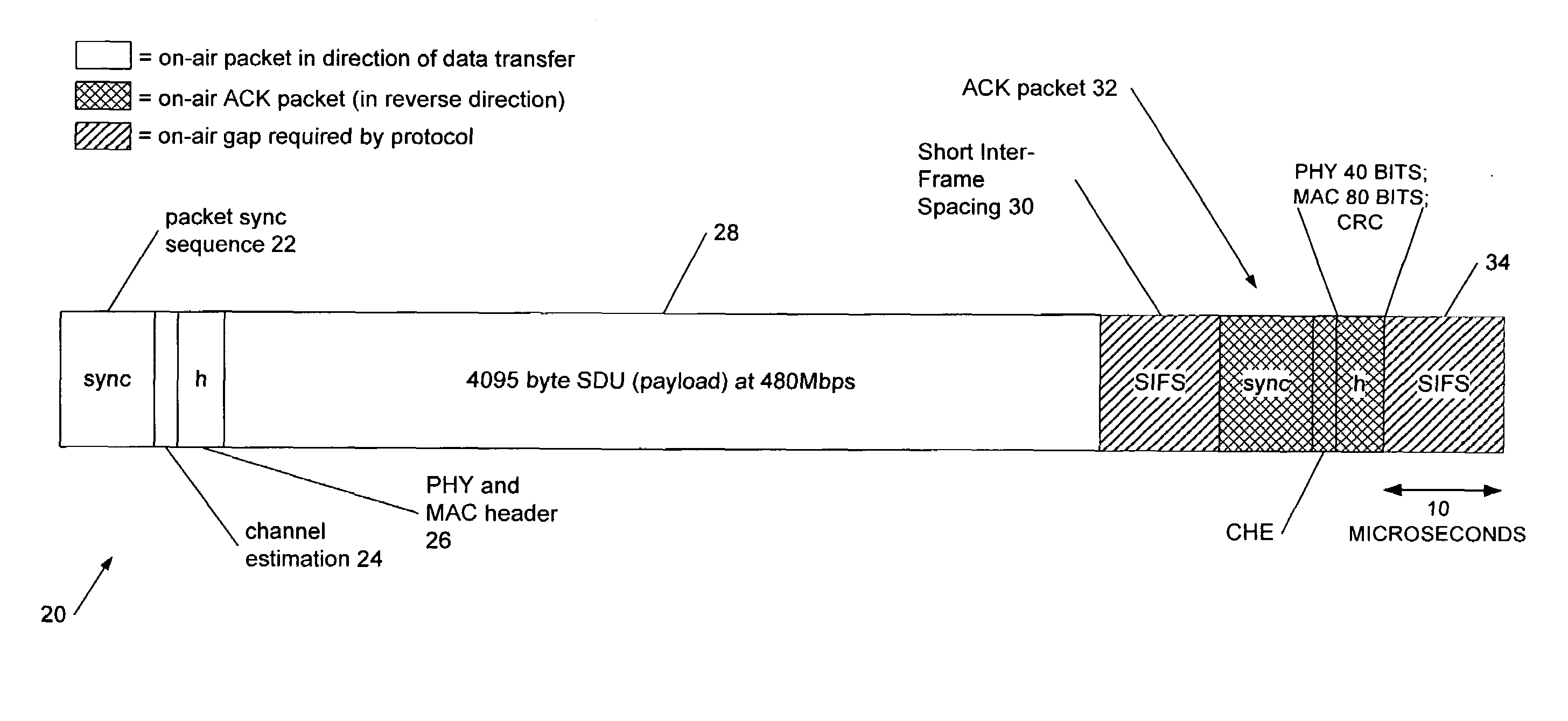
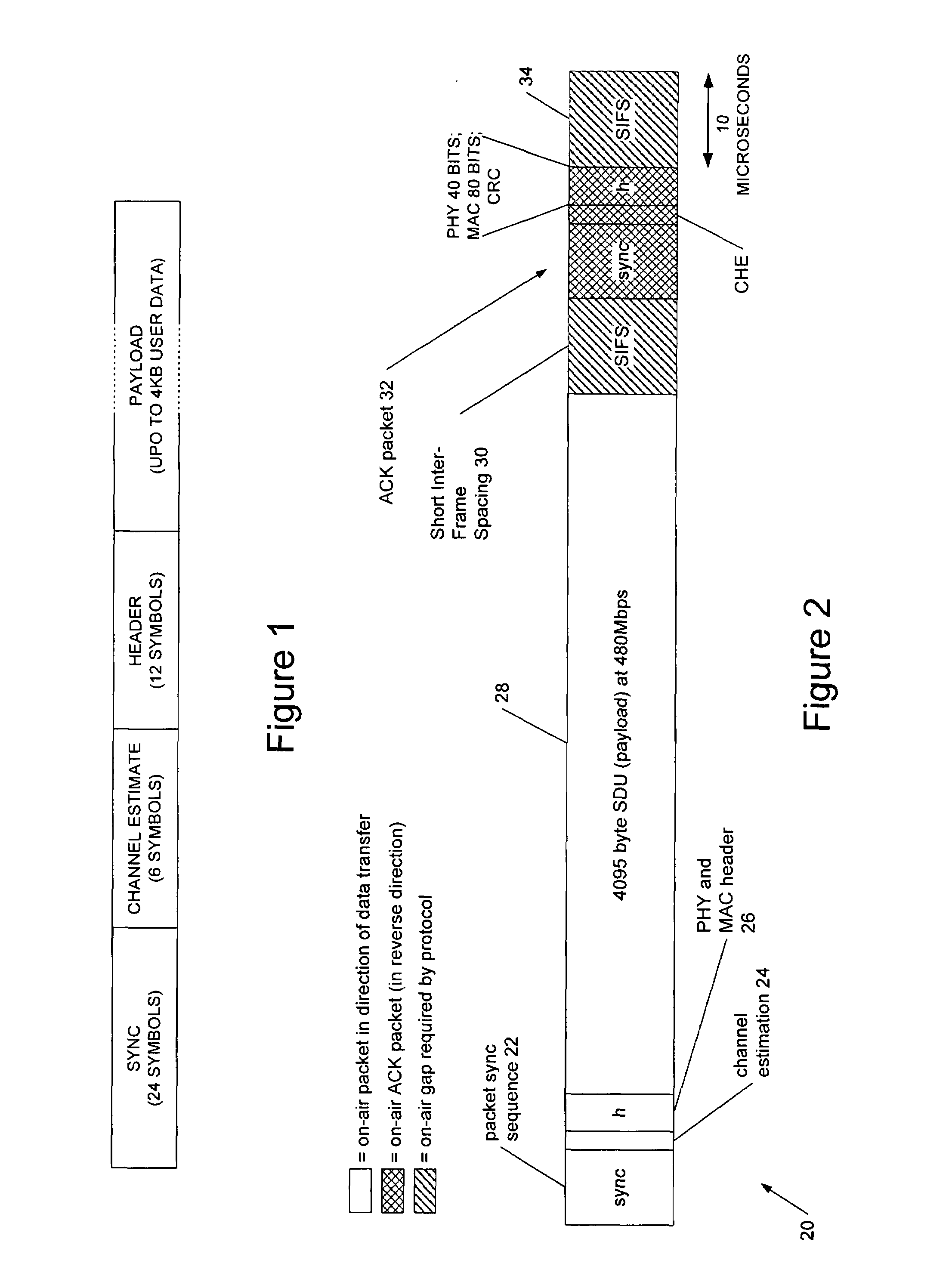
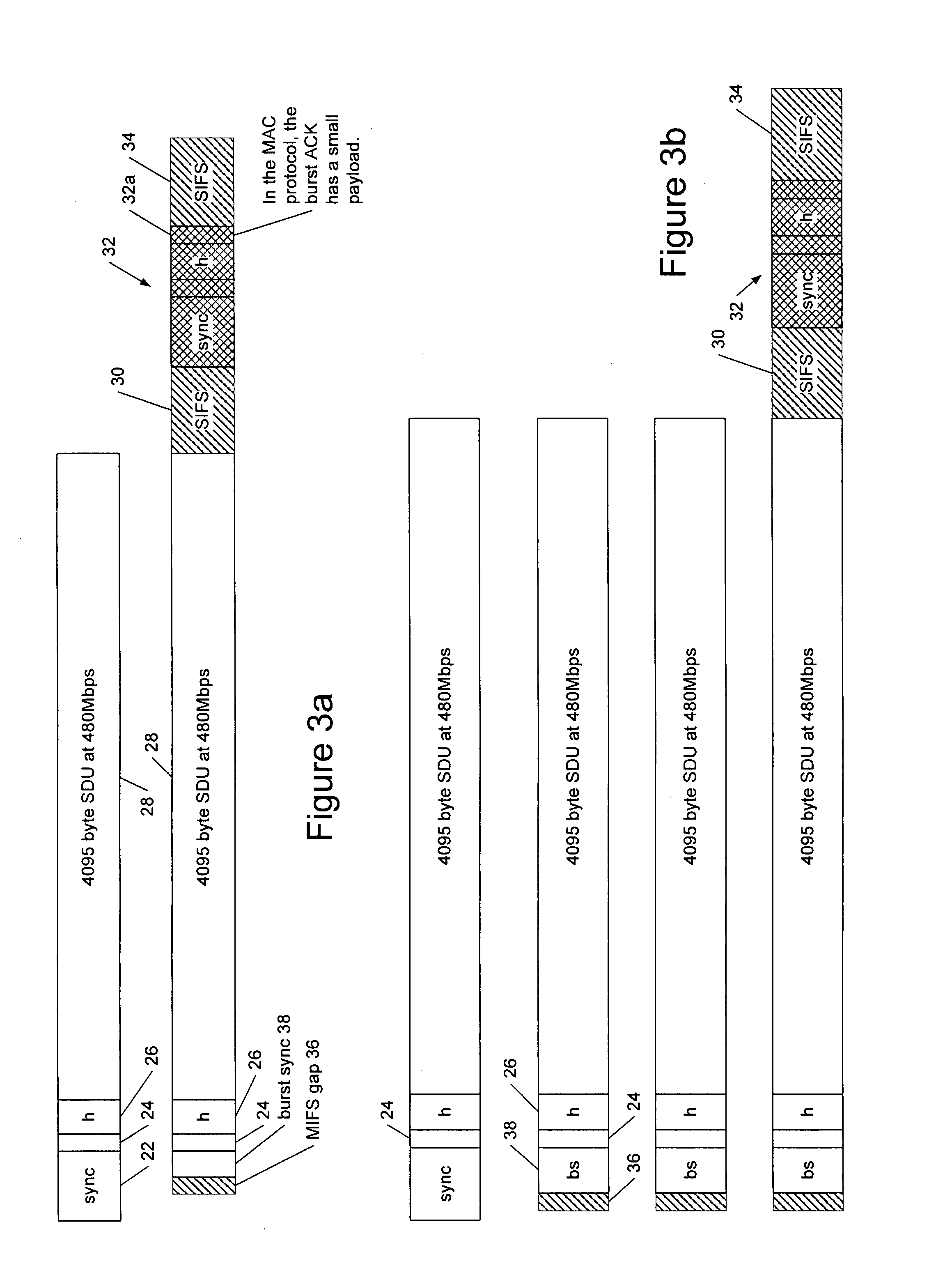
[0014]An advantage of using OFDM synchronisation symbols to send the acknowledgement data is that in embodiments of the method there is no need to perform an FFT on the received data—instead the acknowledgement data can be obtained directly from the synchronisation portion of the receiver in the sending transceiver. In embodiments of the method the acknowledgement data is thus encoded using only synchronisation symbols.
[0015]More particularly in embodiments of the method the acknowledgement data is encoded by modulating a sequence of the synchronisation symbols with a cover sequence. The cover sequence may comprise a sequence of +1 and −1 values (normal or inverted / 180° phase shift) which multiplies the synchronisation symbols. A UWB receiver has a synchronisation module towards the front end which is able to detect whether a synchronisation symbol is normal or inverted or, more particularly, is able to detect a relative inversion (or phase shift) of one synchronisation symbol with respect to another, and thus the acknowledgement data may be retrieved from this synchronisation module effectively directly. In embodiments this facilitates very high speed acquisition of the acknowledgement data and means that there is no need for conventional OFDM demodulation. More particularly therefore, in embodiments, the encoding of the acknowledgement data uses a differential code comprising inverted and non-inverted versions of the synchronisation symbols.
[0027]In embodiments of the protocol, although synchronisation symbols are generally transmitted at a high or maximum level to enable them to easily be detected, preferably the synchronisation symbols comprising the acknowledgement data are transmitted at a reduced signal level, less than the maximum, for example to achieve at the sending transceiver substantially the same level as the channel estimate, header or payload symbols of the data burst have at the receiving transceiver sending the acknowledgement (i.e. approximately reciprocal gain, similar for the sending and receiving transceivers). As previously mentioned, the PHY specification defines hopping between the bands of a band group but in embodiments of the protocol such hopping may not be required if the signal level of the acknowledgement data is reduced, for example as previously described. Thus in embodiments of the protocol frequency hopping is not used when communicating the acknowledgement data. This facilitates decoding of the acknowledgement data using the synchronisation circuitry in the sending transceiver.
[0039]The skilled person will understand that applications of this aspect of the invention (unlike some of the described embodiments) do not require bursts or sync-only ack packets. In embodiments it gains by reducing turnaround time. However preferred implementations require that both ACK and NAK response packets be legitimate. Implementations of embodiments of this aspect of the invention can be tied to a header bit in the tx packet, saying “immediate ack requested”. This permits the receiving PHY to start to send an immediate reply, even before the decoding of the payload has been completed.
[0040]When receiving the ACK or NAK, the data transmitting PHY can be placed in a mode which starts the transmission of the next data packet before the ACK or NAK has been decoded. This will further reduce the inter-packet delays, but (preferably) entirely under control of the data-sending PHY. The ACK or NAK packet may optionally have a further bit or flag that determines whether this is permissible, and / or multi-bit information requesting a delay. This can give the receiving station some ability to control the rate. For low cost devices moving huge volumes of data, active flow control can reduce the need for buffering. At multi-gigabit speeds data buffering can become the dominant silicon cost in the presence of quite small real-time delays.

Problems solved by technology

In particular in a wireless local or personal area network there is a risk that a “third partytransmitter could send a sequence of synchronisation symbols which would appear to be acknowledgement data acknowledging that a data packet had been correctly received.

Method used


Image

  • Ultra wideband communications systems
  • Ultra wideband communications systems
  • Ultra wideband communications systems

Examples


Embodiment Construction

[0056]Referring now to FIG. 4, this shows, schematically, a burst mode protocol according to an embodiment of the invention, which the inventor refers to as a “dense burst” mode. A burst 400 comprising eight data packets 400a-h is shown and like elements to those previously described are indicated by like reference numerals. Thus it can be seen that the initial packet 400a corresponds to that shown in FIG. 3a but the subsequent protocol differs. More particularly, although there is a MIFS gap 36 after the first data packet, this gap is occupied by acknowledgement data 402 after each subsequent packet of the burst except for the last when the protocol, in one embodiment, concludes similarly to before. The protocol does not, in fact, conclude precisely the same way since the final acknowledgement 404 may either comprise an acknowledgement of the last two packets of the burst (either separately so that an acknowledgement of each of the last two packets can be distinguished, or together...


PUM


Abstract

The invention relates to communications protocols for very high-speed data transmission, in particular burst mode packet data communications for ultra wideband (UWB) communications systems. We describe a method of sending a burst of data packets from a first OFDM transceiver to a second OFDM transceiver, said transceivers having a set of OFDM synchronisation symbols for synchronising communications between the transceivers, the method comprising: sending said data packets from said first to said second transceiver, and between sending at least some of said data packets of said bursts receiving acknowledgement data from said second transceiver at said first transceiver; and wherein said acknowledgement data is encoded using said OFDM synchronisation symbols.

Description

BACKGROUND OF THE INVENTION[0001]1. Field of the Invention[0002]This invention relates to communications protocols for very high-speed data transmission, in particular burst mode packet data communications for ultra wideband (UWB) communications systems.[0003]2. Background Art[0004]The MultiBand OFDM (orthogonal frequency division multiplexed) Alliance (MBOA), more particularly the WiMedia Alliance, has published a standard for a UWB physical layer (PHY) for a wireless personal area network (PAN) supporting data rates of up to 480 Mbps. This document was published as, “MultiBand OFDM Physical Layer Specification”, release 1.1, Jul. 14, 2005; release 1.2 is now also available. The skilled person in the field will be familiar with the contents of this document, which are not reproduced here for conciseness. However, reference may be made to this document to assist in understanding embodiments of the invention. Further background material may be found in Standards ECMA-368 & ECMA-369.[...

Claims


Application Information

Patent Timeline
IPC IPC(8): H04L27/28H04B1/38
CPCH04L27/2613H04L27/2655H04L1/1671
Inventor STOYE, WILLIAM
Owner ARTIMI
Learn More