
Reforming system for combined cycle plant with partial CO2 capture

a technology of a combined cycle plant and a forming system, which is applied in the direction of machines/engines, energy input, energy industry, etc., can solve the problems of high cost, high cost, and difficulty in meeting ever-increasing emissions standards, and achieve the effect of capturing such large amounts of co2 and saving costs

Inactive Publication Date: 2008-07-03
GENERAL ELECTRIC CO
View PDF8 Cites 158 Cited by
  • Summary
  • Abstract
  • Description
  • Claims
  • Application Information

AI Technical Summary

Benefits of technology

"The patent describes a system and method for generating power and capturing carbon dioxide from natural gas. The system includes a reformer, shift reaction unit, carbon dioxide removal unit, and gas turbine. The method involves reforming a mixed fuel stream, converting carbon monoxide to carbon dioxide, removing carbon dioxide, and using the heat from the gas turbine exhaust stream to generate steam. The technical effects of the patent are improved efficiency and reduced carbon dioxide emissions from natural gas combined cycle systems."

Problems solved by technology

While these plants produce significantly less CO2 then coal-fired power plants, difficulty remains in meeting the ever-increasing emissions standards.
At such temperatures, the SMR reformer would need to be made of costly high temperature alloys.
Capturing such large amounts of CO2 would be costly and bring down the overall efficiency of the plant, as more fuel would be required to capture the excess CO2 emissions.

Method used


Image

  • Reforming system for combined cycle plant with partial CO2 capture
  • Reforming system for combined cycle plant with partial CO2 capture
  • Reforming system for combined cycle plant with partial CO2 capture

Examples


Embodiment Construction

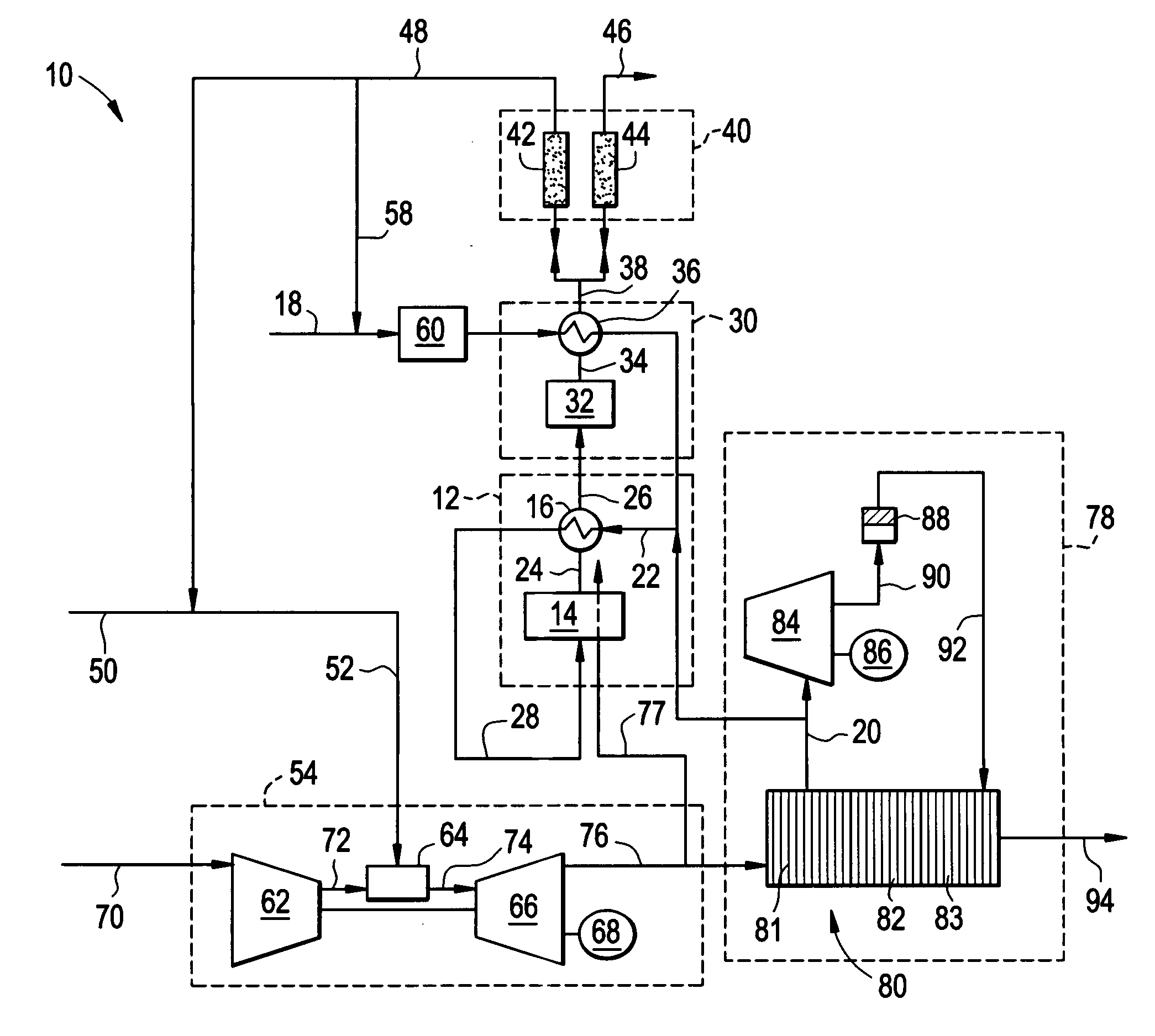
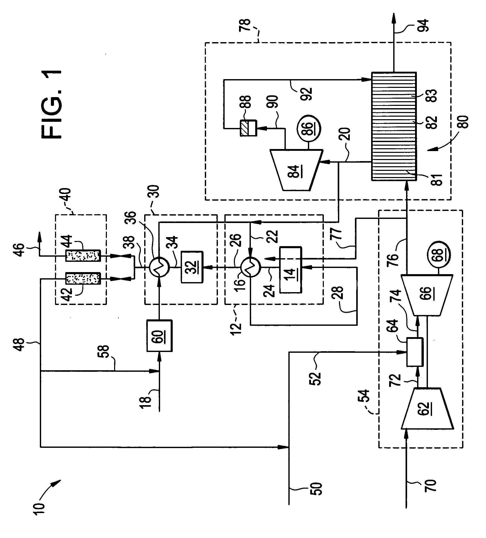
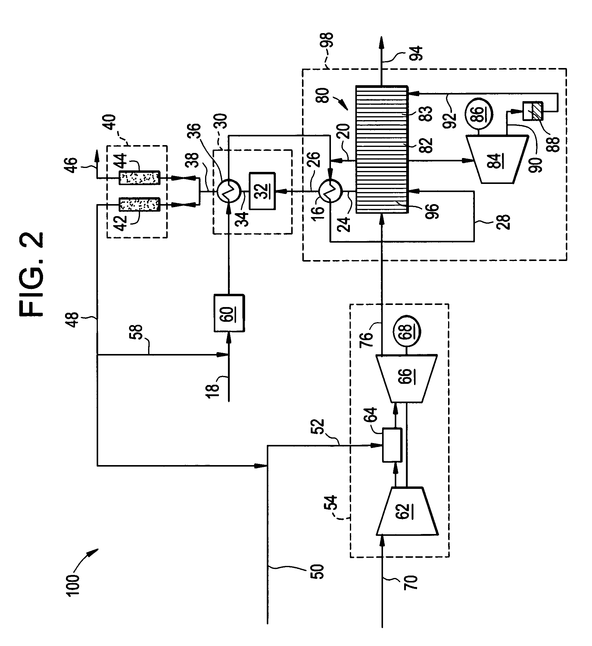
[0011]Combined cycle power systems and processes utilizing pre steam-methane-reformers (SMR) and partial CO2 capture units are disclosed herein. The combined cycle system combines the Rankine (steam turbine) and Brayton (gas turbine) thermodynamic cycles by using heat recovery to capture the energy in the gas turbine exhaust gases for steam production. In contrast to prior art combined cycle plants using conventional reformers, the systems and methods disclosed herein advantageously use a low-temperature pre-SMR to reform only a portion of natural gas (NG) for capture of CO2 emissions over a specified allowance. In conventional SMRs the reaction must occur under high temperatures, e.g., greater than 1,000 degrees Celsius (° C.) for full conversion of the methane to hydrogen. In the pre-SMR disclosed herein, however, reaction temperatures are about 550° C. to about 800° C., specifically about 600° C. to about 750° C., even more specifically 650° C. Because it is desired to capture le...


PUM

PropertyMeasurementUnit
temperatureaaaaaaaaaa
temperaturesaaaaaaaaaa

Abstract

A combined cycle system includes, a pre-steam-methane-reformer operating at a temperature of less than about 800 degrees Celsius to reform a mixed fuel stream to generate a first reformate stream, a water-gas-shift reactor to convert carbon monoxide in the first reformate stream to carbon dioxide and form a second reformate stream, a carbon dioxide removal unit for removing carbon dioxide from the second reformate stream and form a carbon dioxide stream and a third reformate stream; wherein less than about 50 percent of the carbon contained in the mixed fuel stream is recovered as carbon dioxide by the removal unit, a gas turbine unit for generating power and an exhaust stream, and a steam generator unit configured to receive the exhaust stream, wherein the heat of the exhaust stream is transferred to a water stream to generate the steam for the mixed fuel stream and for a steam turbine.

Description

BACKGROUND[0001]Carbon dioxide (CO2), one of the so-called greenhouse gases, is produced during the combustion of fossil fuels in furnaces and power plants. Recent scientific studies have shown that emissions of CO2 and other greenhouse gases, such as methane (CH4) and nitrogen oxides (N2O), can have a significant effect on climate change. The prospect of climate change caused, at least in part, by emission of CO2 and other greenhouse gases has led to international concern and to international treaties, such as the Kyoto Protocol.[0002]Because of the national and international concern, power producers have been attempting to reduce the levels of CO2 produced by power plants. Many newer power plants are combined cycle plants fired by natural gas, or “NGCC” plants. While these plants produce significantly less CO2 then coal-fired power plants, difficulty remains in meeting the ever-increasing emissions standards. Recently, policy makers in Europe proposed creation of a maxima quota of...

Claims


Application Information

Patent Timeline
Patent Type & Authority Applications(United States)
IPC IPC(8): F01K25/06F02G3/00C07C27/04B01J19/00
CPCF01K23/06Y02E20/16Y02C10/04C01B3/384C01B3/48C01B2203/0233C01B2203/0475C01B2203/0833C01B2203/142C01B2203/84Y02P20/10Y02P20/129Y02P30/00Y02C20/40B01D53/00Y02P80/15
Inventor LIU, KEBOWMAN, MICHAEL JOHNSANBORN, STEPHEN DUANEEVULET, ANDREI TRISTAN
Owner GENERAL ELECTRIC CO
Learn More