Gas Generator

a generator and gas technology, applied in the direction of electric fuzes, explosives, pedestrian/occupant safety arrangements, etc., can solve the problems of delayed ignition of gas generators, airbags that cannot exhibit sufficient performance, low ignitability of gas generators, etc., and achieve low cost, simple structure, and small size

Inactive Publication Date: 2008-07-03
NIPPON KAYAKU CO LTD
View PDF13 Cites 17 Cited by
  • Summary
  • Abstract
  • Description
  • Claims
  • Application Information

AI Technical Summary

Benefits of technology

[0034]The above-described gas generator is capable of igniting an ignition material stably at a high-speed but low energy by using a squib in which a thin-film bridge is buried into a plug in such a manner that the surface of the thin-film bridge is kept approximately on a level with the head of the electrode pin and the surface of the header part of the plug.
[0035]Further, since a gas generator equipped with a squib including a thin-film bridge of the present invention is simple in structure, it can be made small in size and also manufactured at a low cost.
[0036]Still further, a gas generator according to the pyro inflator method, which is equipped with a squib including a thin-film bridge of the present invention, is capable of inflating an airbag faster than a conventional counterpart, when used in an airbag for side impact.
[0037]In addition, a gas generator according to the hybrid inflator method, which is equipped with a squib including a thin-film bridge of the present invention, is more prominently effective in inflating and deploying an airbag in a shorter time, which is characteristic of the hybrid inflator method.
[0038]In a side collision of vehicles, an impact absorbing part, which is called a crush zone, is smaller and a distance between a passenger and an interior trim is shorter than in a front collision. Therefore, an airbag for side impact and a curtain airbag must be deployed more instantaneously than an airbag for dealing with a front collision and deployed before the passenger contacts with the interior trim. Thus, a gas generator for a side collision must be instantaneously activated in response to an electrical activating signal from an ECU (electronic control unit) which detects the side collision. The present invention has been made for satisfying the above requirement, in which a thin-film bridge is used in a resistance heating element of a squib, thereby making it possible to reduce an ignition time several times or more than a dozen times, as compared with a conventional bridge wire. However, a squib using a conventional thin-film bridge has problems on electrical connections, as described above. The invention has solved the problems by keeping the bridge surface of the thin-film bridge on a level with the surface of a header part of a plug and also has provided an electrostatic measure by electrically connecting an electrode pad of the thin-film bridge with a metal part of the header part of the plug.

Problems solved by technology

Where gas generant compositions include low reactive materials such as guanidine derivatives and ammonium nitrate as its compositions, there poses a problem that the gas generants are low in ignitability, in addition to a slow burning velocity.
Therefore, only a slight delay in activation of the gas generator will give such a serious impact that the airbag cannot exhibit a sufficient performance.
Gas generants, which are low in ignitability, will take a longer time to ignite on a squib inside the gas generator, resulting in a delayed ignition of the gas generator.
However, the thus increased quantity of the propellant will lead to an increase in total calorific value of the gas generator itself, which consequently increases the weight of a filter member for cooling the gas and makes the gas generator larger in size.
Under these circumstances, conventional gas generators have not been made smaller in size or lighter in weight.
However, this gas generator needs a process for notching the outer peripheral end surface of the partition member to provide the seal member such as the O-ring, thereby increasing a cost of manufacturing the gas generator, which poses a problem.
However, since the gas generator must keep a high pressure gas in a gas cylinder, the high pressure gas may escape from the gas cylinder in the course of as long as 15-year life period as a gas generator, thereby resulting in a failure of providing a sufficient effect, where sealing is insufficient.
This structure is able to rupture the rupture diaphragm without fail but requires a hollow piston or the like, thereby making the gas generator structurally complicated, which also poses a problem.
However, an increased quantity of the propellant requires a chamber for accommodating the propellant, thereby making it difficult to miniaturize the gas generator.
Further, in this instance, it is difficult to rupture the rupture disk simultaneously with ignition of the squib.
This generator is unable to sufficiently heat the gas from the gas cylinder, which poses another problem.
However, where the squib is connected with an electric-conductive epoxy resin and used in a gas generator for an automobile, it is exposed to a high-temperature environment on blazingly hot days in summer, which may result in a change in resistance value of the electric-conductive epoxy resin.
Further, the resistance value is easily affected by the surface condition of an electrode even at an initial stage of assembly, resulting in a great variance in initial resistance value, which poses a problem.

Method used


Image

  • Gas Generator
  • Gas Generator
  • Gas Generator

Examples


first embodiment

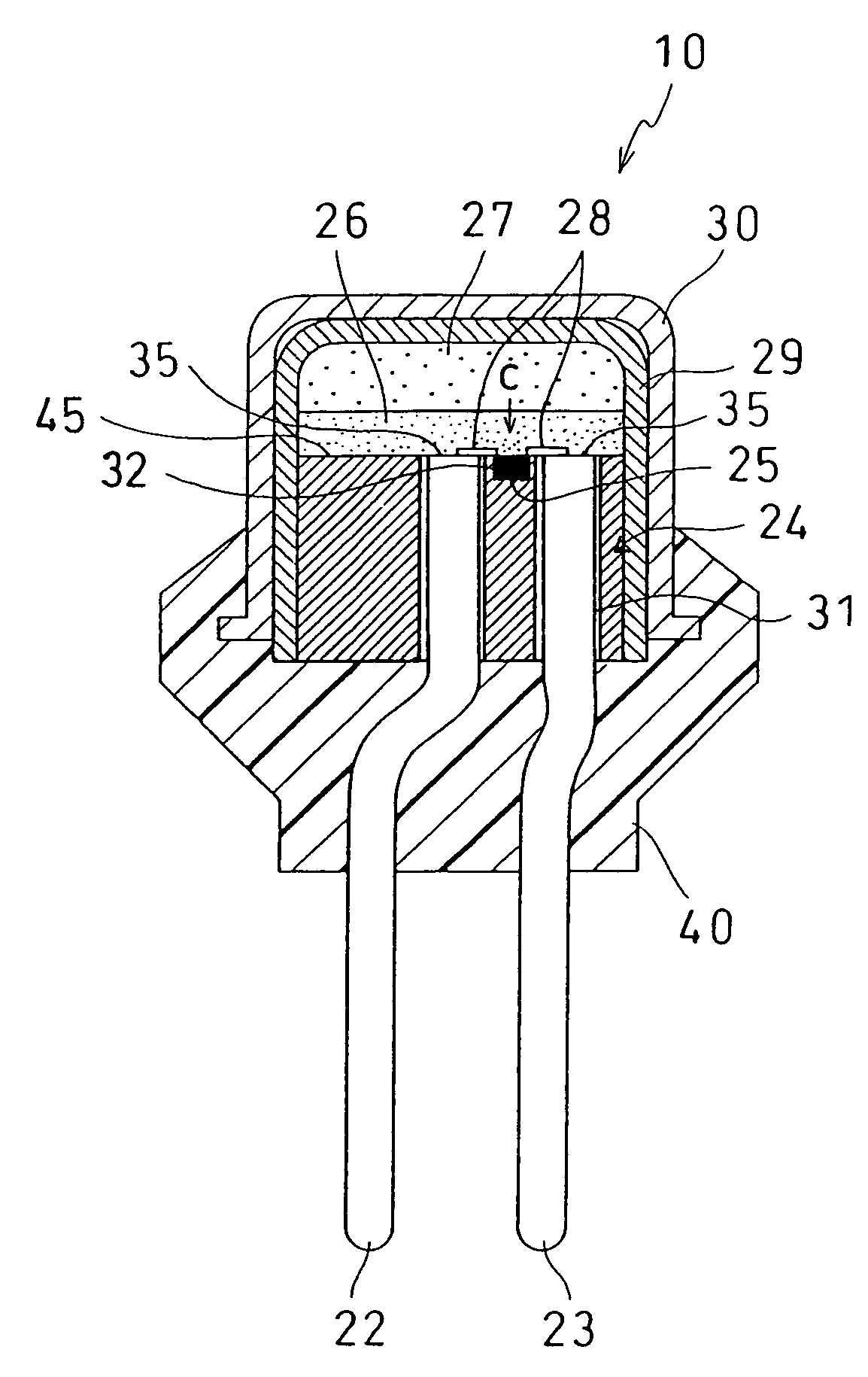
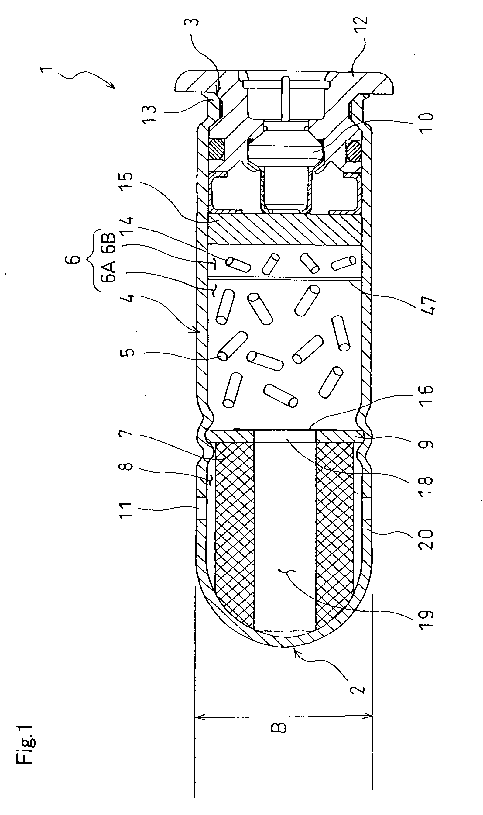
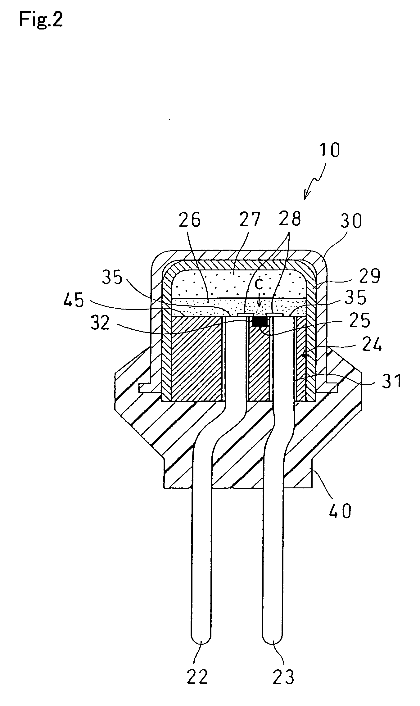
[0039]An explanation will be made for an example of the gas generator according to the present invention with reference to drawings. FIG. 1 is across-sectional view showing an example of one embodiment of a gas generator according to the present invention. In FIG. 1, a gas generator 1 is a gas generator according to a so-called pyro inflator method, provided with a housing 4, a first partition member 9 which divides the inside of the housing 4 into a combustion chamber 6 which seals gas generants 5 for generating a high temperature gas by burning and a filter chamber 8 to which a filter member 7 is attached, and a squib 10 which ignites and burns the gas generants 5 inside the combustion chamber 6, in which the housing 4 is in a closed-end cylindrical shape, which is opened at the one end 3 and closed at the other end 2.

[0040]An outer container of a conventional gas generator is constituted with a total of five parts, namely, three parts consisting of a housing, a lid on the one end...

second embodiment

[0093]Next, an explanation will be made for a gas generator 46 of a second embodiment according to the present invention with reference to FIG. 6. It is noted that in the present invention, the same symbols are given to parts common to those of the gas generator 1 of the first embodiment to omit a detailed explanation.

[0094]The gas generator 46 of the present invention is different from the gas generator 1 of the first embodiment illustrated in FIG. 1 in that the other end 2 of the housing is in a flat-bottomed shape and gas discharge openings 11 are arranged axially in two lines. Despite the above arrangement, as with the gas generator 1 of the present invention, the gas generator 46 can be decreased in number of parts because the other end 2 is closed and only the one end 3 needs to be sealed. Further, the gas generator 46 can be increased in safety and made smaller in size because the sealed part is only the one end 3.

[0095]In addition, in the gas generator 46 of the present inve...

third embodiment

[0097]Next, an explanation will be made for a gas generator 50 of a third embodiment according to the present invention with reference to FIG. 7. It is noted that in the present invention, the same symbols are given to parts common to those of the gas generator 1 of the first embodiment to omit a detailed explanation.

[0098]In FIG. 7, the gas generator 50 is a gas generator according to the so-called hybrid inflator method, and provided with a gas cylinder 51 containing a high pressure gas, a housing 54 which houses a propellant 52 and a squib 10, an outer cylindrical member 55 which connects and holds the gas cylinder 51 and the housing 54, a filter member 57 provided along an inner periphery of the outer cylindrical member 55.

[0099]The gas cylinder 51 is made of a metal such as stainless steel or aluminum, available in a cylindrical shape having a closed end, and contracted diametrically in two stages on the opening side. Argon, helium gas and others are loaded inside the gas cylin...


PUM

PropertyMeasurementUnit
outer diameteraaaaaaaaaa
diameteraaaaaaaaaa

Abstract

A gas generator including a plug (24) having a header part (45) and two or more electrode pins (22, 23), a thin-film bridge (25) having electrode pads (41, 42), and a squib (10) in which upon supply of electric current to the thin-film bridge (25) via the electrode pins (22, 23), the thin-film bridge (25) is activated to ignite ignition materials (26, 27), wherein the thin-film bridge (25) is arranged into a hollow (32) prepared at the plug (24) in such a manner that the thin-film bridge (25) is kept approximately on a level with the head (35) of the electrode pins (22, 23) and the header part (45) of the plug (24), the thin-film bridge (25) is connected by wire bonding to the electrode pins (22, 23) at the electrode pad parts (41, 42), and at least either of the electrode pad (41) or (42) of the thin-film bridge (25) is connected by the wire bonding to a metal part of the header part (45) of the plug (24).

Description

TECHNICAL FIELD[0001]The present invention relates to a gas generator suitable for inflating an airbag for side impact, a curtain airbag and the like.BACKGROUND ART[0002]An airbag is known as a safety system for protecting a passenger from an impact resulting from a collision of an automobile. The airbag is activated by a large quantity of a high-temperature and high-pressure gas generated by a gas generator. Conventionally, gas is generated by gas generators according to two roughly-categorized methods. One is a pyro inflator method in which all gases are generated by burning solid gas generants (for example, refer to Patent Document 1). The other is a hybrid inflator method in which a gas cylinder containing a high pressure gas and a small quantity of explosive compositions for supplying heat to a high pressure gas in the gas cylinder are used to discharge a large quantity of a high pressure gas (for example, refer to Patent Document 4).[0003]Where gas generant compositions includ...

Claims


Application Information

Patent Timeline
Patent Type & Authority Applications(United States)
IPC IPC(8): F42C19/12F42C11/00B01J7/00B60R21/26B60R21/264C06B29/02C06B31/02C06B31/28C06C7/00C06C9/00C06D5/00C06D5/06
CPCB60R21/2644B60R2021/26029F42B3/124C06D5/06C06C9/00
Inventor YOSHIDA, MASAHIROMAEDA, SHIGERUIWASAKI, MAKOTOKODAMA, RYOI
Owner NIPPON KAYAKU CO LTD
Why Eureka
Try Eureka