
Apparatus and method for detecting surface plasmon resonance

a surface plasmon and apparatus technology, applied in the field of image phase apparatus and a method for detecting the surface plasmon resonance, can solve the problems of increasing the the complexity of the fabricating method, and the relatively high building cost of the instrument, so as to reduce the difficulty of fabrication and subsequent maintenance, reduce the manufacturing cost, and reduce the sampling time

Inactive Publication Date: 2008-07-03
IND TECH RES INST
View PDF7 Cites 15 Cited by
  • Summary
  • Abstract
  • Description
  • Claims
  • Application Information

AI Technical Summary

Benefits of technology

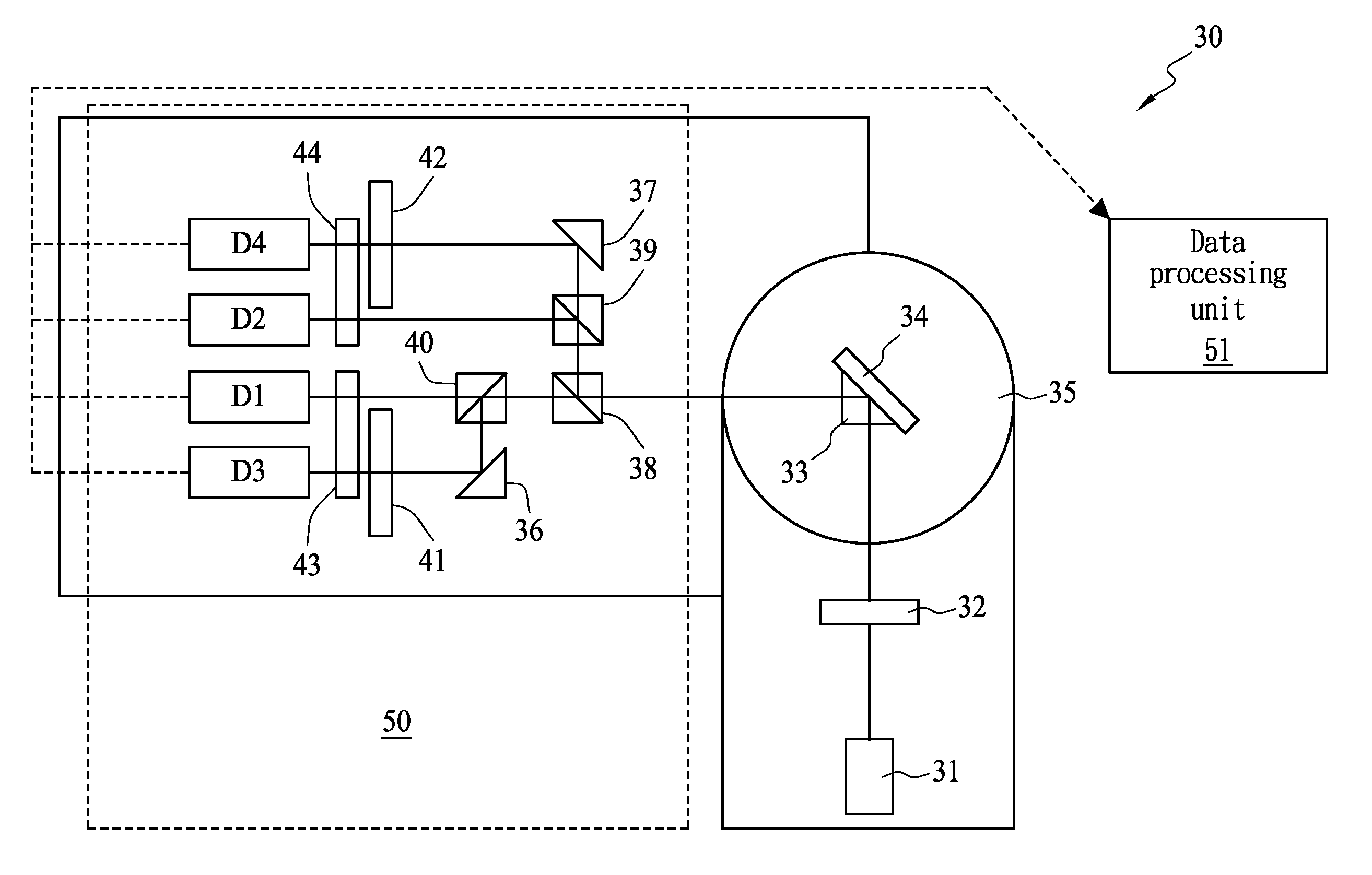
[0010]The present invention provides a full-field image phase-detecting technique using SPR, so as to measure, for example, a biomolecular reaction. In the present invention, there is no need for a PZT driving element or a multi-wavelength light source, and a phase can be obtained without performing correction and compensation, thereby simplifying the apparatus and reducing the cost.
[0013]According to the SPR detection of the present invention, the light intensity signals of four phases are taken, and the phase to be detected is calculated by a numerical method similar to the five-step phase-shifting method on principle. The advantage of this method lies in the fact that the objective of resolving the phase can be achieved merely through utilizing optical elements, i.e., there is no need for additional light sources or driving mechanisms, thereby reducing manufacturing costs, and decreasing fabrication and subsequent maintenance difficulties. In addition, unlike the five-step phase-shifting method that needs to take images five times to obtain the signal, the present invention takes required images once, so that sampling time can be reduced. Compared with the former cases, the present invention resolves the phase without performing correction and compensation, and therefore, it is simpler and more precise.

Problems solved by technology

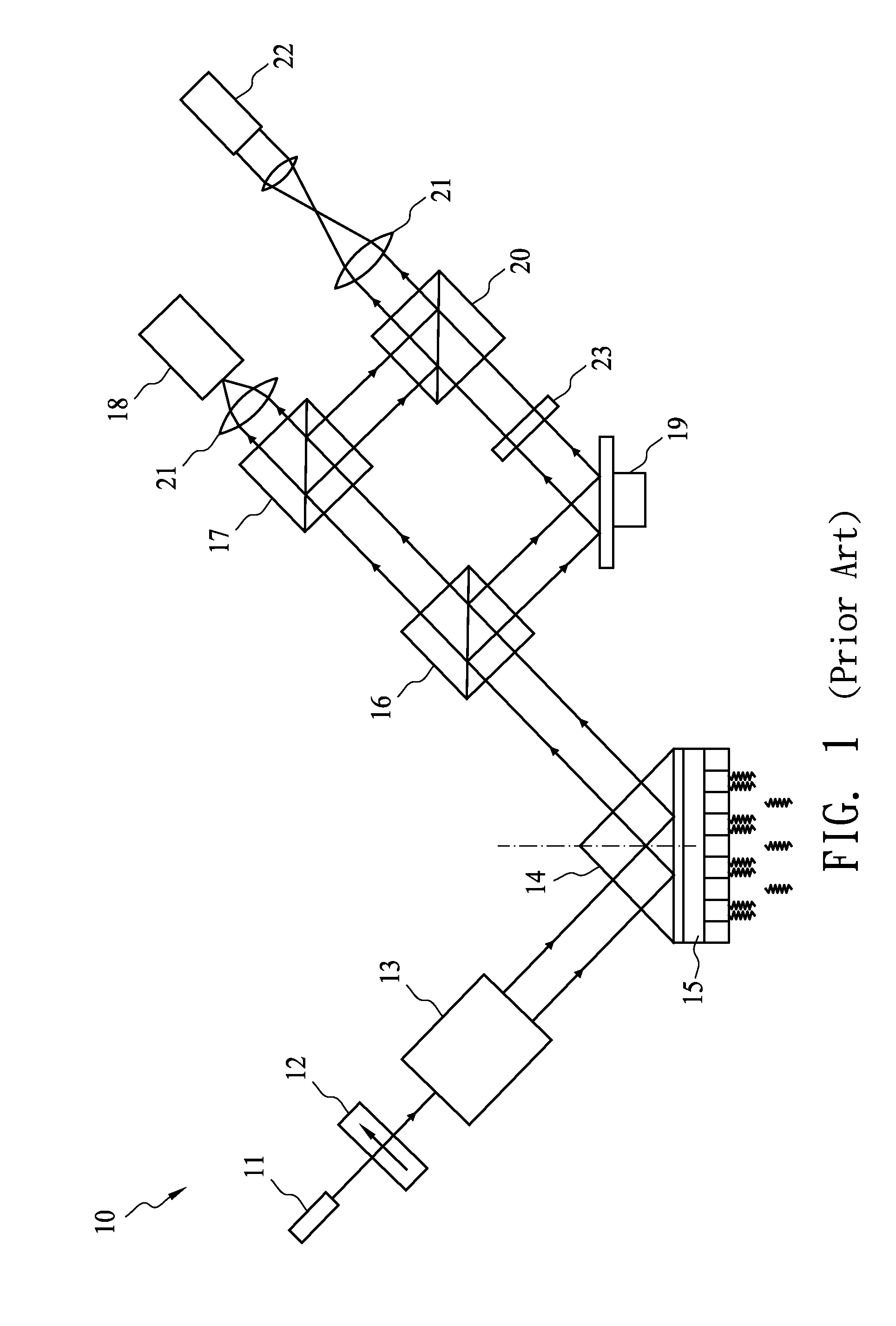
The disadvantage of this method lies in the fact that the price of the current PZT driving element is relatively high, and a high voltage power source is required for the PZT element, so the cost of the instrument will increase.
For the above two processes, the fabricating method is complex and the building cost for the instrument is relatively high.
In addition, as to the five-step phase-shifting method, it is necessary to take five images to calculate a set of meaningful data, so sampling time is relatively long.

Method used


Image

  • Apparatus and method for detecting surface plasmon resonance
  • Apparatus and method for detecting surface plasmon resonance
  • Apparatus and method for detecting surface plasmon resonance

Examples


Embodiment Construction

[0022]The present invention is described in detail below according to the sequence of basic principles, system architecture of phase-resolving technique, theoretical analysis, and refractive index distribution simulation.

[0023]Basic Principles

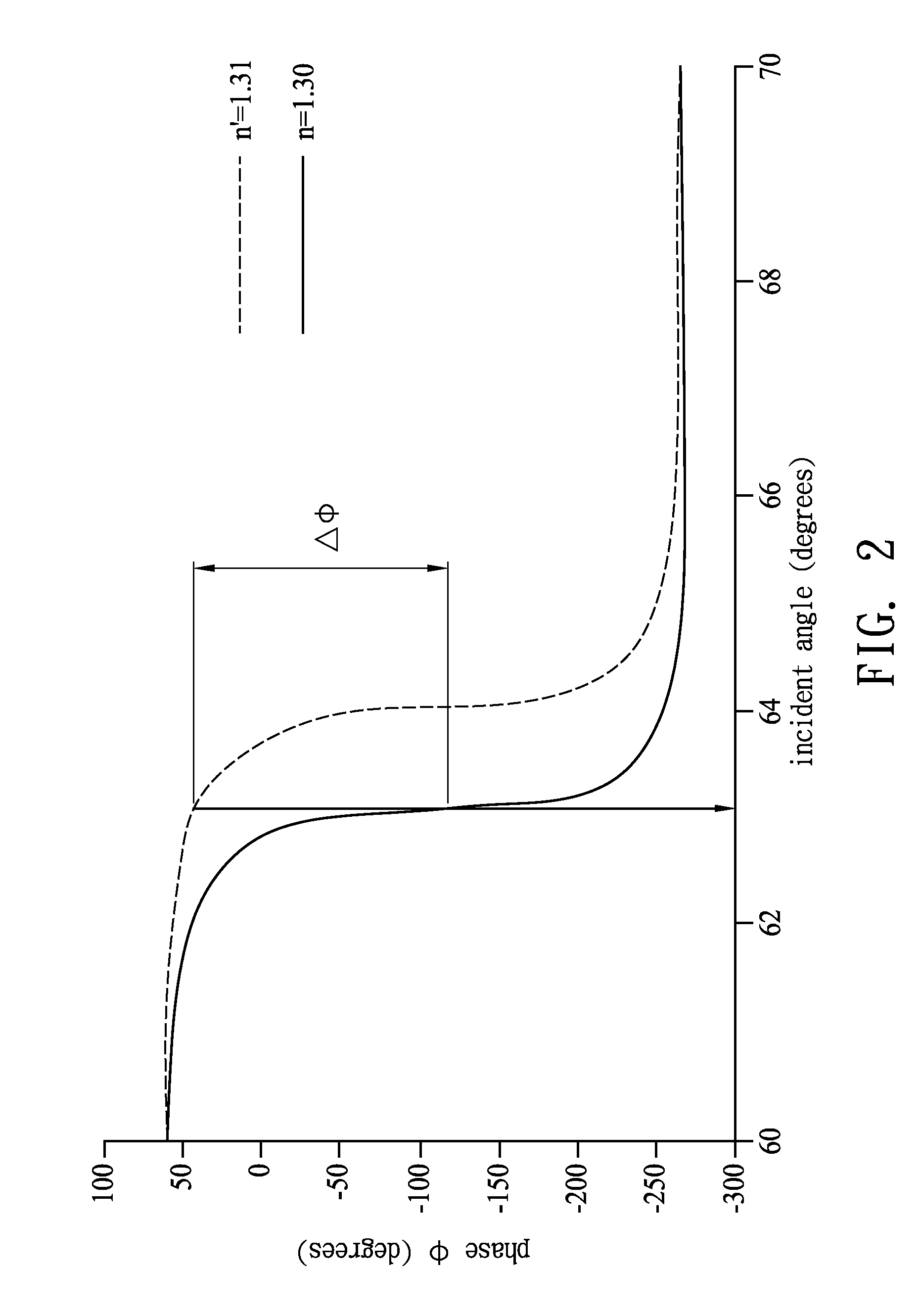
[0024]SPR occurs between a dielectric material and a metal film, and the horizontal polarization component (P polarized light) of the incident light source energizes free electrons of the metal film to generate the longitudinal resonance movement, and this movement is transferred along a medium surface, which is surface plasmon wave (SPW). According to the SPR theory, if the horizontal component kx of the wave vector k0 for the P polarized light is equal to the wave vector ksp of the SPW, SPR is generated, as in the following formula (I):

kx=k0ɛg(λ)sin(θ)=k0ɛm(λ)·n2ɛm(λ)+n2=ksp,(1)

[0025]θ indicates an incident angle, λ indicates a wavelength of an incident light, ∈g(λ) indicates a dielectric coefficient of the coupling prism, ∈m(λ) indicates a d...


PUM

PropertyMeasurementUnit
refractive indexaaaaaaaaaa
surfaceaaaaaaaaaa
SPRaaaaaaaaaa

Abstract

An apparatus for detecting surface plasmon resonance (SPR) comprises a light source, a light-coupling unit, a phase-resolving module, and a data-processing unit. The light source provides a light beam emitting into a surface of a metal film to generate surface plasmon resonance. The phase-resolving module is configured to split the reflection light of the light beam on the surface of the metal film into a first light, a second light, a third light, and a fourth light, and to detect the intensities of the lights simultaneously. The phases of the first light and second light differentiate by 90 degrees, and the phases of the third light and fourth light differentiate by 90 degrees. The data-processing unit calculates the phase variation of the surface plasmon resonance on the metal film based on the intensities of the first light, second light, third light, and fourth light.

Description

BACKGROUND OF THE INVENTION[0001](A) Field of the Invention[0002]The present invention relates to an apparatus and a method for detecting surface plasmon resonance (SPR). More particularly, the present invention relates to an image-phase apparatus and a method for detecting the SPR.[0003](B) Description of the Prior Art[0004]The physical characteristics will change slightly while there are inter biomolecules interactions happening on the surface of bio-thinfilm. If such tiny physical change can be detected by certain means of technique, the techniques became a method of analyzing biomolecular interactions.[0005]With the development and combination of optical technology and Micro-Electro-Mechanical Systems (MEMS), various biosensing technologies have been developed, for example, Confocal Laser Scanning Fluorescence microscopy (CLSFM), Quartz Crystal Micro-balance (QCM), Surface Plasmon Resonance (SPR), etc. Among them, SPR technology has the highest sensitivity of interfacial bio-int...

Claims


Application Information

Patent Timeline
Patent Type & Authority Applications(United States)
IPC IPC(8): G01N21/00
CPCG01N21/553G01N21/21
Inventor LEE, JU YISHIH, HSUEH-CHINGHONG, C.T.
Owner IND TECH RES INST
Learn More