Fluidized Bed Reactor with Back-Mixing for Dehydrogenation of Light Paraffins

a technology of back-mixing and fluidized bed reactor, which is applied in the direction of furnaces, physical/chemical process catalysts, lighting and heating apparatus, etc., can solve the problems of limited conversion rate, high cost of operation and maintenance, and very fast reaction and reversibility, so as to reduce capital and operating costs, simplify process design, and reduce the effect of capital and operating costs

Active Publication Date: 2008-07-03
UOP LLC
View PDF7 Cites 44 Cited by
  • Summary
  • Abstract
  • Description
  • Claims
  • Application Information

AI Technical Summary

Benefits of technology

[0007]Accordingly, it is an object of the present invention to provide a catalytic dehydrogenation system and process with reduced capital and operating costs and greater conversion and selectivity. It is a further object of the present invention to provide a catalytic dehydrogenation system and process with simplified process design.
[0008]We have discovered a catalytic dehydrogenation system and process in which capital and operating costs are reduced, product conversion and selectivity are increased, and process design is simplified by using a back-mixed fluidized bed reactor. In a preferred embodiment of the present invention, an alkane-rich stream is fed to a single reactor stage in which the alkane-rich stream is contacted with a fluidized bed of catalyst. Deactivated catalyst is withdrawn from the reactor and sent to a regenerator where coke is burned off the catalyst to regenerate it. Additional fuel is also burned in the regenerator to raise the temperature

Problems solved by technology

The reaction is very fast and reversible and conversion rates are limited by the thermodynamic equilibrium conditions.
Frequent cycling of the system can lead to operational and maintenance problems and the non-continuous system is less thermally efficient than a continuous process.
It has long been recognized in industry that conventional catalytic dehydrogenation systems suffer from a variety of drawbacks.
This increases the complexity and capital costs of the catalytic dehydrogenation system.
Capital costs are also increased in conventional systems by the need to have multiple rea

Method used


Image

  • Fluidized Bed Reactor with Back-Mixing for Dehydrogenation of Light Paraffins
  • Fluidized Bed Reactor with Back-Mixing for Dehydrogenation of Light Paraffins
  • Fluidized Bed Reactor with Back-Mixing for Dehydrogenation of Light Paraffins

Examples


example

[0020]An engineering simulation was used to develop a comparison of the present invention to the conventional moving bed reactor system to illustrate the advantages of the present invention.

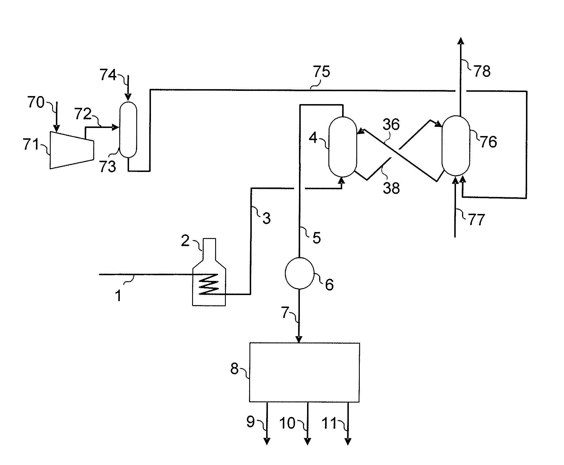
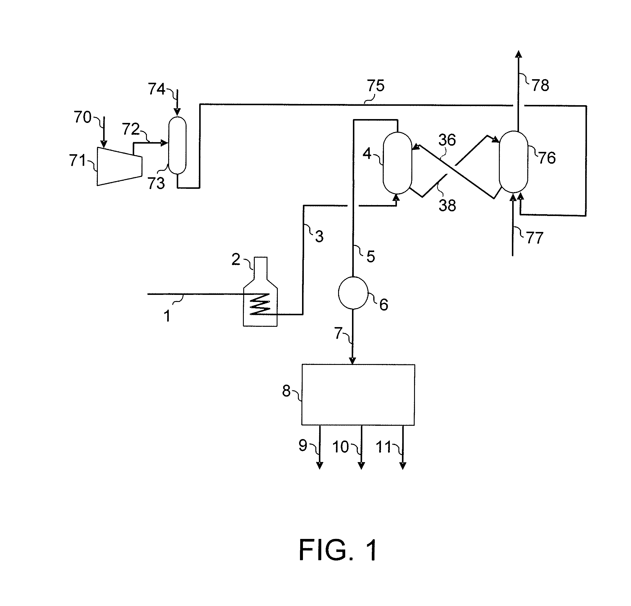
[0021]In the base case process of the prior art, a mixture of hydrogen and propane is fed to a system of four adiabatic reactors with interheaters between each reactor. The temperature at the inlet of each reactor is 655° C. The pressure at the outlet of the final reactor is 170 kPa (10 psig). The process achieves a conversion of 40% of the propane, with 84% molar selectivity to propylene (moles of propylene formed per mole of propane reacted). In the process of the invention a mixture of hydrogen and propane is fed to a single-stage back-mixed reactor with inlet temperature of 632° C. and outlet pressure of 170 kPa (10 psig). The process achieves a conversion of 40% of the propane with 96% molar selectivity to propylene.

[0022]Although a preferred embodiment of the present invention has been desc...


PUM

PropertyMeasurementUnit
Temperatureaaaaaaaaaa

Abstract

An improved process and system for the endothermic dehydrogenation of an alkane stream is described. The process and system of the present invention comprise a back-mixed fluidized bed reactor. The alkane stream is dehydrogenated in a single reactor stage by contacting the alkane stream with a back-mixed fluidized bed of catalyst. Deactivated catalyst is withdrawn from the back-mixed fluidized reactor and heated to produce hot regenerated catalyst. The hot regenerated catalyst is returned to the back-mixed fluidized bed reactor at a rate sufficient to maintain the back-mixed fluidized bed reactor at substantially isothermal conditions.

Description

CROSS-REFERENCE TO RELATED APPLICATION[0001]This application claims priority from Provisional Application No. 60 / 882,349 filed Dec. 28, 2006, the contents of which are hereby incorporated by reference.FIELD OF THE INVENTION[0002]This invention relates to a catalytic dehydrogenation process and system with improved conversion and selectivity and lower operating and installation costs.BACKGROUND OF THE INVENTION[0003]The catalytic dehydrogenation of alkanes (paraffin hydrocarbons) to produce alkenes (olefin hydrocarbons) is an important and well known hydrocarbon conversion process in the petroleum refining industry. This is because alkenes are generally useful as intermediates in the production of other more valuable hydrocarbon conversion products. For example, propylene can be used in the production of polymers and propylene glycol, butylenes can be used in the production of high octane motor fuel and isobutylenes can be used to produce methyl-t-butyl ether, a gasoline additive.[00...

Claims


Application Information

Patent Timeline
IPC IPC(8): C07C5/333
CPCC07C5/324C07C5/325C07C2523/755C07C2523/75C07C2523/745C07C2521/04C07C2521/08C07C2521/16C07C2523/26C07C2523/28C07C2523/30C07C2523/36C07C2523/42C07C2523/44C07C11/02Y02P20/584
Inventor GLOVER, BRYAN K.ZARRAGA, JULIE A.SCHULTZ, MICHAEL A.
Owner UOP LLC
Why Eureka
Try Eureka