Method for microstructure control of ceramic thermal spray coating

a technology of ceramic thermal spray coating and microstructure control, which is applied in the direction of superimposed coating process, liquid/solution decomposition chemical coating, machines/engines, etc., can solve the problems of blade tip detrimental to turbine efficiency, complete elimination of leakage, and designers of gas turbine engines go to great lengths to devise effective sealing structures, etc., to promote vertical crack propagation

Inactive Publication Date: 2008-07-10
UNITED TECH CORP
View PDF15 Cites 35 Cited by
  • Summary
  • Abstract
  • Description
  • Claims
  • Application Information

AI Technical Summary

Benefits of technology

[0012]In accordance with the present invention, a method of forming a segmented ceramic spray coating on a substrate broadly comprises (1) providing one or more heat sources disposed proximate to a substrate; (2) depositing optionally a quantity of a bond coat material into a heat stream of the one or more heat sources and onto a deposition area of a surface of the substrate to form an optional bond coat layer; (3) depositing optionally a quantity of a first ceramic material into the heat stream of the one or more heat sources and onto the deposition area of the surface to form an optional first ceramic material layer upon the optional bond coat layer; (4) applying the heat stream to a preheated thermal gradient zone located in front of the deposition area of a surface of the first ceramic material layer to expand the optional first ceramic material; (5) depositing one or more quantities of additional ceramic material into the heat stream upon the pre-heated, expanded optional first ceramic material layer to form one or more additional layers of ceramic material; (6) cooling one or more additional layers of ceramic materials to promote vertical crack propagation; and (7) applying the heat stream to the pre-heated thermal gradient zone of a surface of the one or more additional layers of ceramic material to expand the additional ceramic material. Steps 5 through 7 may be repeated one or more times, if desired.

Problems solved by technology

Although the duct segments limit the leakage of gas flow around the blade tips, they do not completely eliminate the leakage.
It has been found that even minor amounts of gas flow around the blade tips detrimentally affect turbine efficiency.
Thus, gas turbine engine designers go to great lengths to devise effective sealing structures.
Unfortunately current duct segment coatings, which are typically ceramic, suffer from excessive material loss as a result of erosion or spalling.
In general, erosion is the wearing away of coating material due to factors such as abrasion and corrosion.
Erosion often results from particle impingement during engine operation.
Spalling or spallation is typically caused by delamination cracking at the ceramic-metal interface resulting from thermal stress and the aggressive thermal environment.
The coating losses due to erosion and spallation result in large part to microcracks present in the segment ceramic coating.
In contrast, vertically oriented microcracks bolster the coating's strain tolerance which prolongs the coating's service life.
Ceramic coating loss increases blade tip clearance and thus is detrimental to turbine efficiency, as well as detrimental to the blades themselves.
For example, the blades may become damaged due to the increased temperature at which the engine must then operate to make up for lost thrust.
These conditions represent a compromise between equipment capability, efficiency and microstructural characteristics of the ceramic coating.
The current process may not always exert adequate active control of the thermal gradients and thermal cycling that occurs in the spray process.
The balance between vertical crack formation and horizontal crack formation is very difficult to control and occurs very randomly.
As a result, shrinkage occurs in more than one direction and thermal cycling causes cracks to form horizontally within the plane of the coating as well as vertically through the coating.
The horizontal cracks that are parallel to the substrate do not improve the coating's strain tolerance and durability; these cracks actually cause the coating to spall off.

Method used


Image

  • Method for microstructure control of ceramic thermal spray coating
  • Method for microstructure control of ceramic thermal spray coating
  • Method for microstructure control of ceramic thermal spray coating

Examples


Embodiment Construction

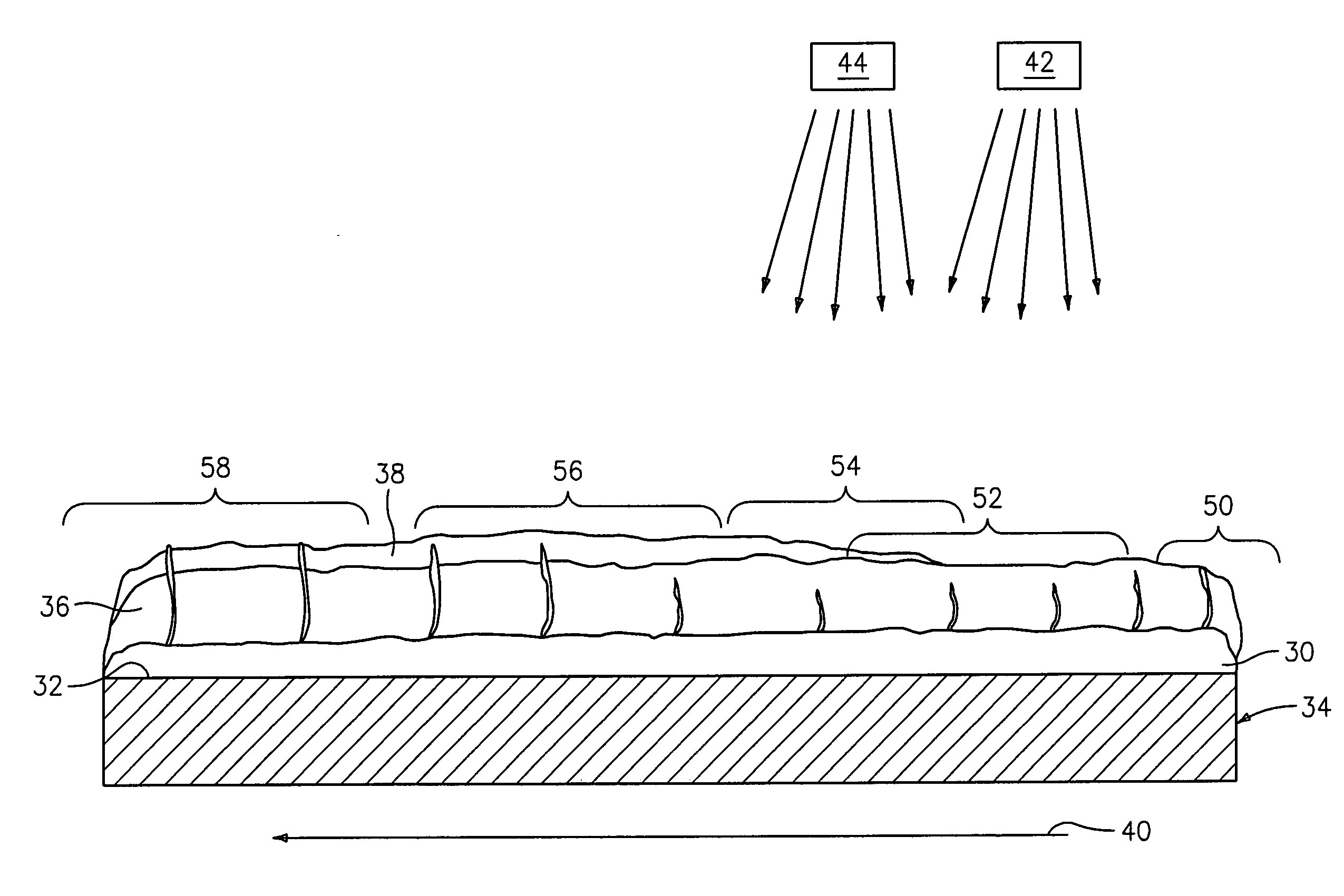
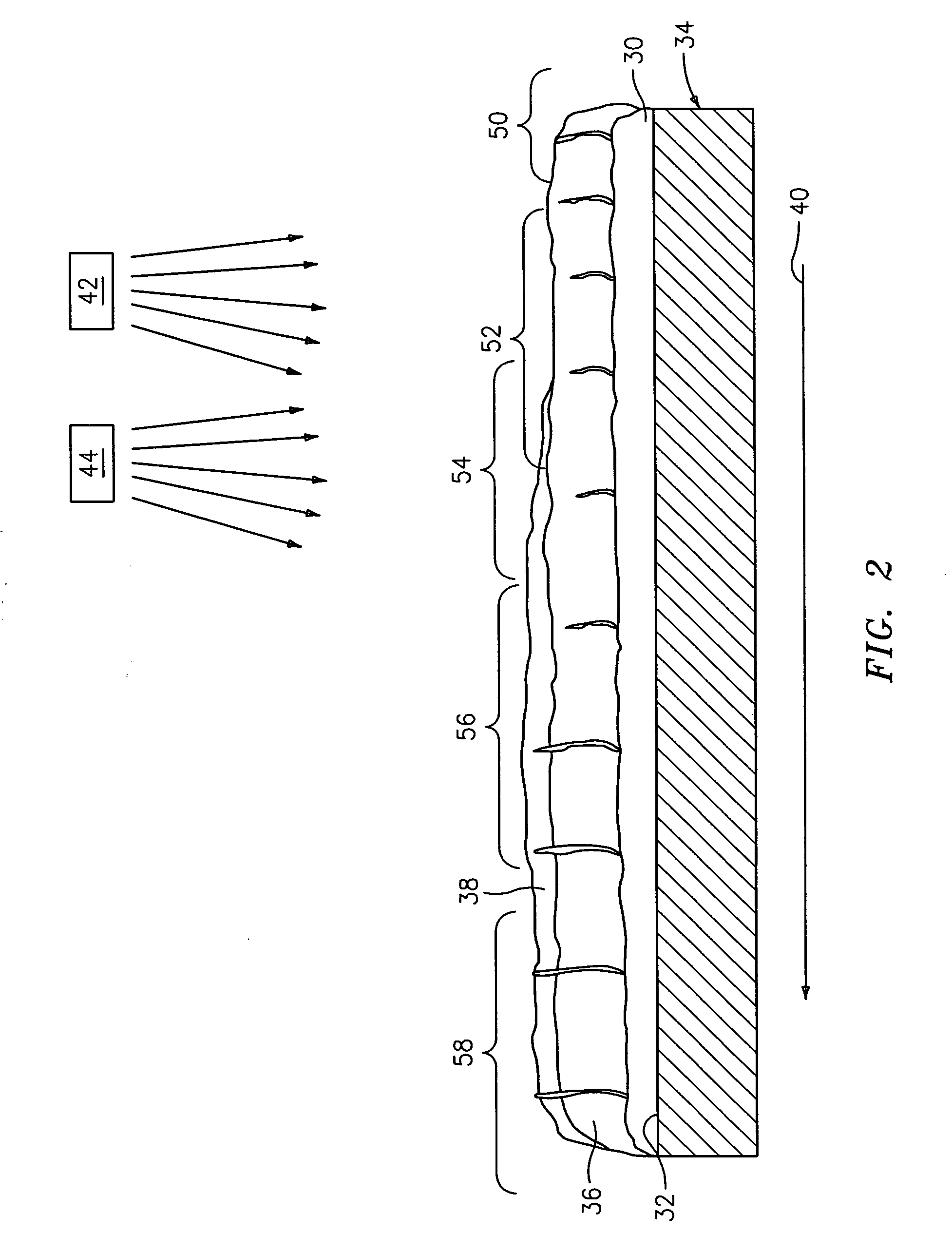
[0022]To improve the quality of ceramic coatings, the methods described herein propose to increase the amount of vertical microcracking present within the coating microstructure. Vertical microcracking provides strain tolerance, which prolongs the coating's service life.

[0023]The terms “equilibrium”, “equilibrate” and their related forms are intended to convey the establishment of temperatures and thermal gradients between the substrate surface and successive coating layers being deposited thereupon in order to promote vertical crack propagation in the coating. During the processes described herein, a repeated cycle of heat flux occurs within the coating layer(s) for a short duration of time, dynamically heating the coating layer surface and causing thermal gradients due to the heat capacities and conductivities of the materials. The thermal gradients are allowed to dissipate over a period of time, for example, as little as a fraction of a second, which causes shrinkage of the depos...


PUM

PropertyMeasurementUnit
pressureaaaaaaaaaa
temperatureaaaaaaaaaa

Abstract

An apparatus for applying segmented ceramic coatings includes means for supporting and moving one or more substrates; one or more heat sources disposed proximate to one or more substrates, wherein at least one of the heat sources is positioned to apply a heat stream to pre-heat a thermal gradient zone on a surface of a substrate; a material deposition device disposed proximate to one or more heat sources, wherein the material deposition device is positioned to deposit a material on a deposition area located behind the thermal gradient zone on the surface; and means for monitoring a surface temperature of one or more substrates.

Description

FIELD OF USE[0001]This invention relates to thermal spray coatings and, more particularly, to controlling crack formation in ceramic coatings.BACKGROUND OF THE INVENTION[0002]Modern gas turbine engines, particularly those used in aircraft, operate at high rotational speeds and high temperatures for increased performance and efficiency. The turbine of a modern gas turbine engine is typically of an axial flow design and includes a plurality of axial flow stages. Each axial flow stage comprises a plurality of blades mounted radially at the periphery of a disk which is secured to a shaft. A plurality of duct segments surrounds the stages to limit the leakage of gas flow around the tips of the blades. These duct segments are located on the inner surface of a static housing or casing. The incorporation of the duct segments improves thermal efficiency because more work may be extracted from gas flowing through the stages as opposed to leaking around the blade tips.[0003]Although the duct s...

Claims


Application Information

Patent Timeline
Patent Type & Authority Applications(United States)
IPC IPC(8): B05C5/00B05D1/02
CPCC23C4/02C23C4/06C23C4/12F01D5/288F01D11/122C23C4/127F05D2240/11F05D2300/21F05D2230/90C23C28/3215C23C28/345Y02T50/672C23C4/134Y02T50/60
Inventor STROCK, CHRISTOPHER W.DAVIS, CHARLES G.
Owner UNITED TECH CORP
Why Eureka
Try Eureka