Integrated stator and rotor for a DC brushless ceiling fan motor

a technology of dc brushless ceiling fans and stators, which is applied in the direction of machines/engines, mechanical equipment, and magnetic circuit shapes/forms/construction, etc., can solve the problems of increasing power consumption and electrical inefficiency, affecting the stability of original product measurements, and inaccuracy of assembly, so as to achieve the effect of increasing efficiency and power saving capabilities

Active Publication Date: 2008-07-17
RHINE ELECTRONICS
View PDF4 Cites 25 Cited by
  • Summary
  • Abstract
  • Description
  • Claims
  • Application Information

AI Technical Summary

Benefits of technology

[0009]The primary object of the present invention is a DC brushless ceiling fan motor containing a stator and motor therein made of permeable material and integrated by a secondary production process. In addition to the integrated stator and rotor structure, the present invention also provides an electrical controlling circuit that drives

Problems solved by technology

1. Poor efficiency: The conventional AC monophase ceiling fan motor uses a shoe box-like electric machinery design. This design type has lower power factors that could result in increased power consumption and electrical inefficiency.
2. High working temperature: As mentioned, due to the lower power factors of the conventional motor design, the efficiency of the motor is lessened. Therefore, after the conventional AC motor has been working at full speed for a short time, the temperature of the inner windings of the motor will rise significantly, up to nearly 100° C. After a short period of use, the insulating materials of the inner motor will wear due to the high temperature and will thus provide less and less insulation over time, further resulting in leakage of electricity and eventually resulting in a short

Method used


Image

  • Integrated stator and rotor for a DC brushless ceiling fan motor
  • Integrated stator and rotor for a DC brushless ceiling fan motor
  • Integrated stator and rotor for a DC brushless ceiling fan motor

Examples


Embodiment Construction

[0021]While this invention is capable of embodiment in many different forms, shown in the drawings and herein described in detail is the preferred embodiment of the invention. The preferred embodiment in disclosed with the understanding that the present description is but one example of the principles of the invention and is not intended to limit the broad aspects of the invention to the single embodiment illustrated.

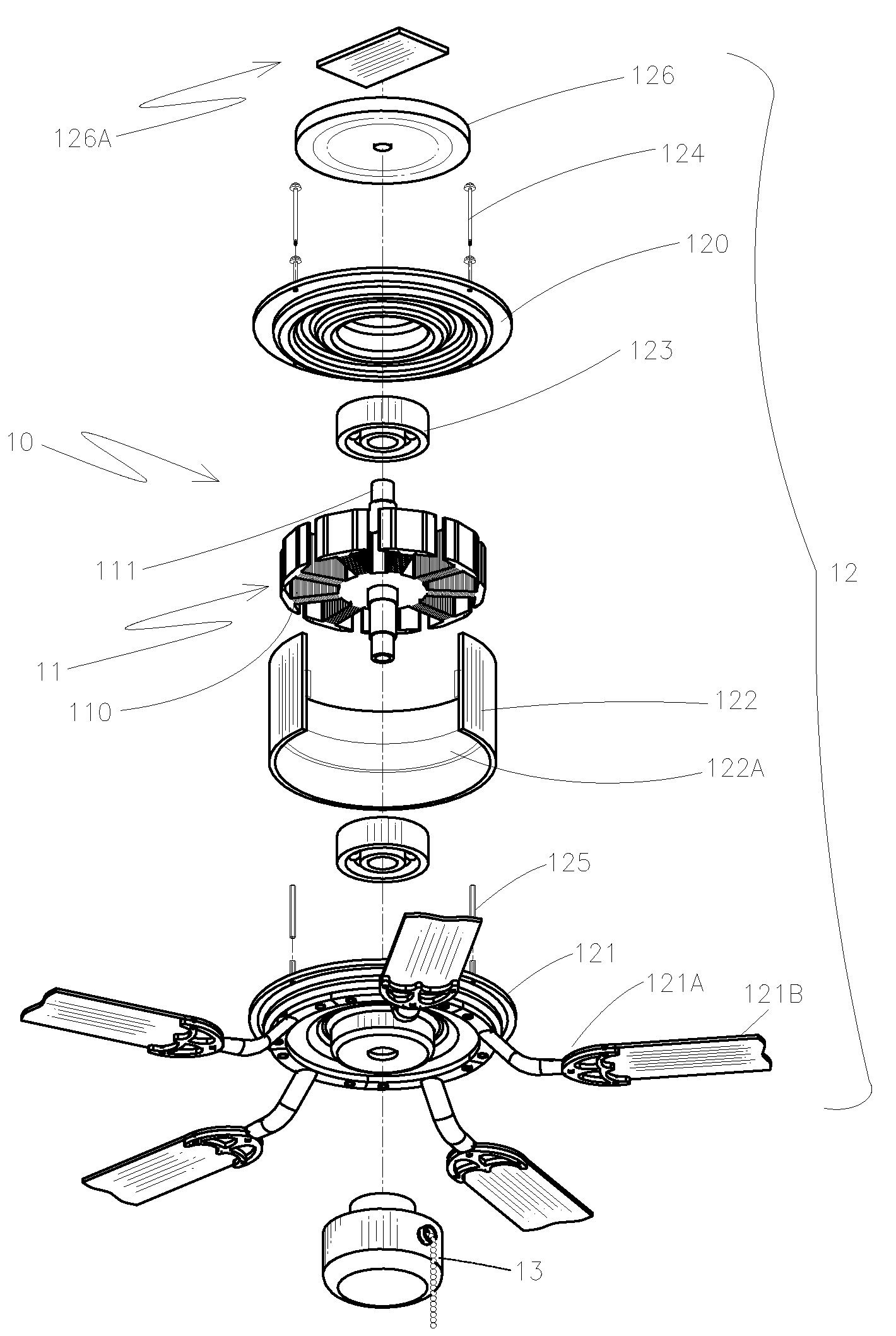
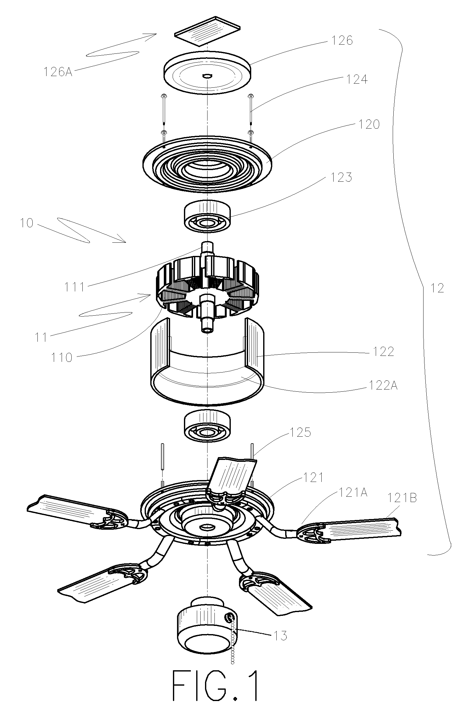
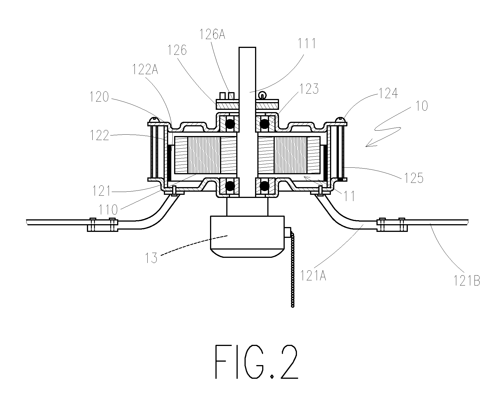
[0022]FIG. 1 is an exploded view of the ceiling fan, FIG. 2 is a cross-sectional view of the motor, FIG. 3 is a flowchart of production, FIG. 4 illustrates the circuitry for a remote control circuit and FIG. 5 illustrates the circuitry for a manual control circuit. The present invention comprises:

[0023]An integral stator 11, wound around a windings 110, and the core of the stator 11 provides a central axle 111. The integral stator 11 is made of a permeable material and is formed by means of a secondary production process 31.

[0024]The rotor 12 includes a top lid 120, a l...


PUM


Abstract

A stator and rotor for a DC brushless ceiling fan motor includes an integrated design of the stator and rotor to form an integrated stator, the integrated stator is made of a permeable material and is formed by means of a secondary production process. The DC brushless ceiling fan motor further includes an electrical controlling circuit that comprises a computer microprocessor, a power supply, a frequency converter, a phase detector and a remote control device or a manual control switch with the purpose of controlling the speed and the orientation of the motor, and thus achieving the result of low working temperature and high electrical efficiency.

Description

BACKGROUND OF THE INVENTION[0001]1. Field of the Invention[0002]The present invention relates to a DC brushless ceiling fan motor. More particularly, the present invention relates to an improvement on the stator and rotor therein.[0003]2. Description of Related Art[0004]In general, a conventional ceiling fan motor has an AC monophase motor design, and the motor stator 40 is made up of a stack of silicon steel laminations 41 formed by a punch machine with an individual thickness of 0.5˜1.0 mm (as shown in FIG. 10). Regarding the process of making such a stator 40, first, every formed silicon steel lamination 41 must be stacked on one another. Second, the rivets are used to secure each silicon steel lamination 41 forming a stacked lamination. Although this kind of method has been used for years, it still has some improvable defects, such as:[0005]1. Poor efficiency: The conventional AC monophase ceiling fan motor uses a shoe box-like electric machinery design. This design type has low...

Claims


Application Information

Patent Timeline
IPC IPC(8): H02P7/29H02K7/14H02K23/66H02K11/00
CPCF04D25/088H02K11/0073H02K7/14H02K11/33
Inventor CHANG, CHUNG-MIN
Owner RHINE ELECTRONICS
Why Eureka
Try Eureka