

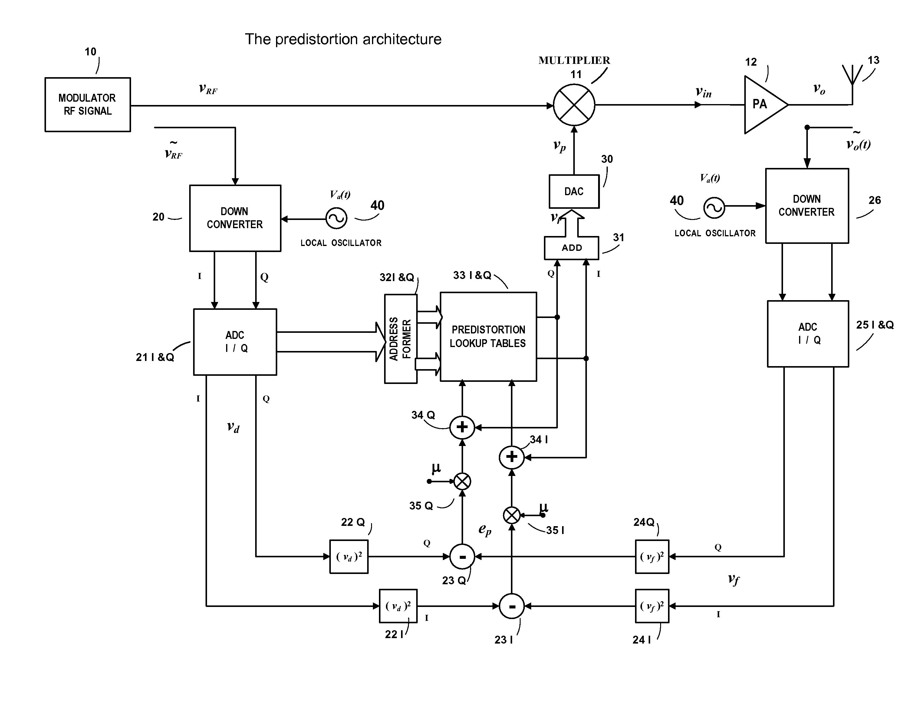
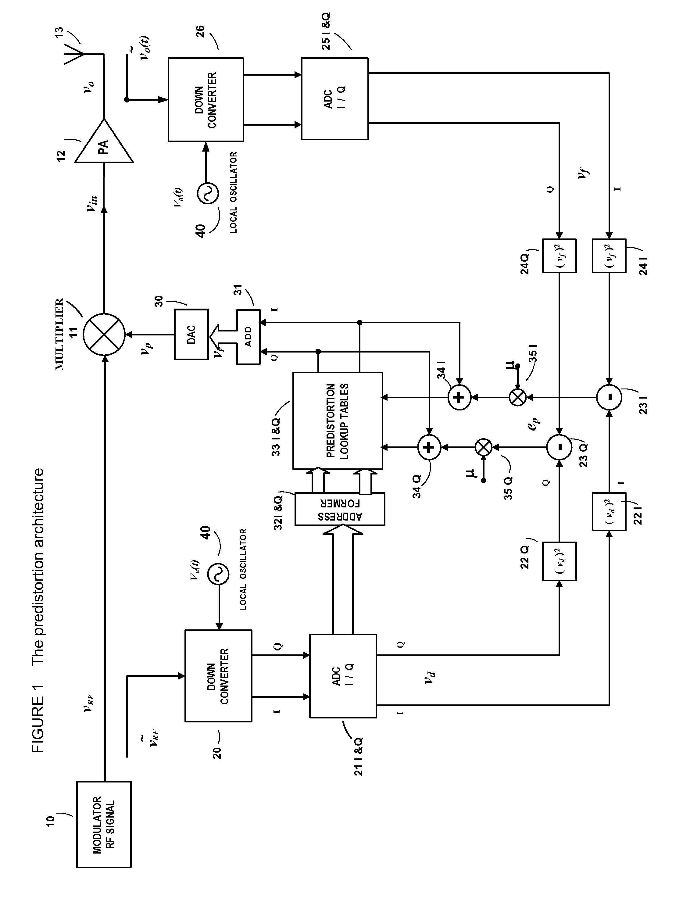
Power Amplifier Time-Delay Invariant Predistortion Methods and Apparatus
a technology of time-delay and power amplifier, which is applied in the field of time-delay invariant predistortion methods and apparatuses of power amplifiers, can solve the problems of difficult to measure in a laboratory such a time-delay parameter, significant problems with respect to the accuracy of predistortion correction, and increase the difficulty of testing such intrinsic time-delay parameters. , to achieve the effect of improving power efficiency and spectrum efficiency, simple circuit structure, and convenient implementation
- Summary
- Abstract
- Description
- Claims
- Application Information
AI Technical Summary
Benefits of technology
Problems solved by technology
Method used
Image

Examples
Embodiment Construction
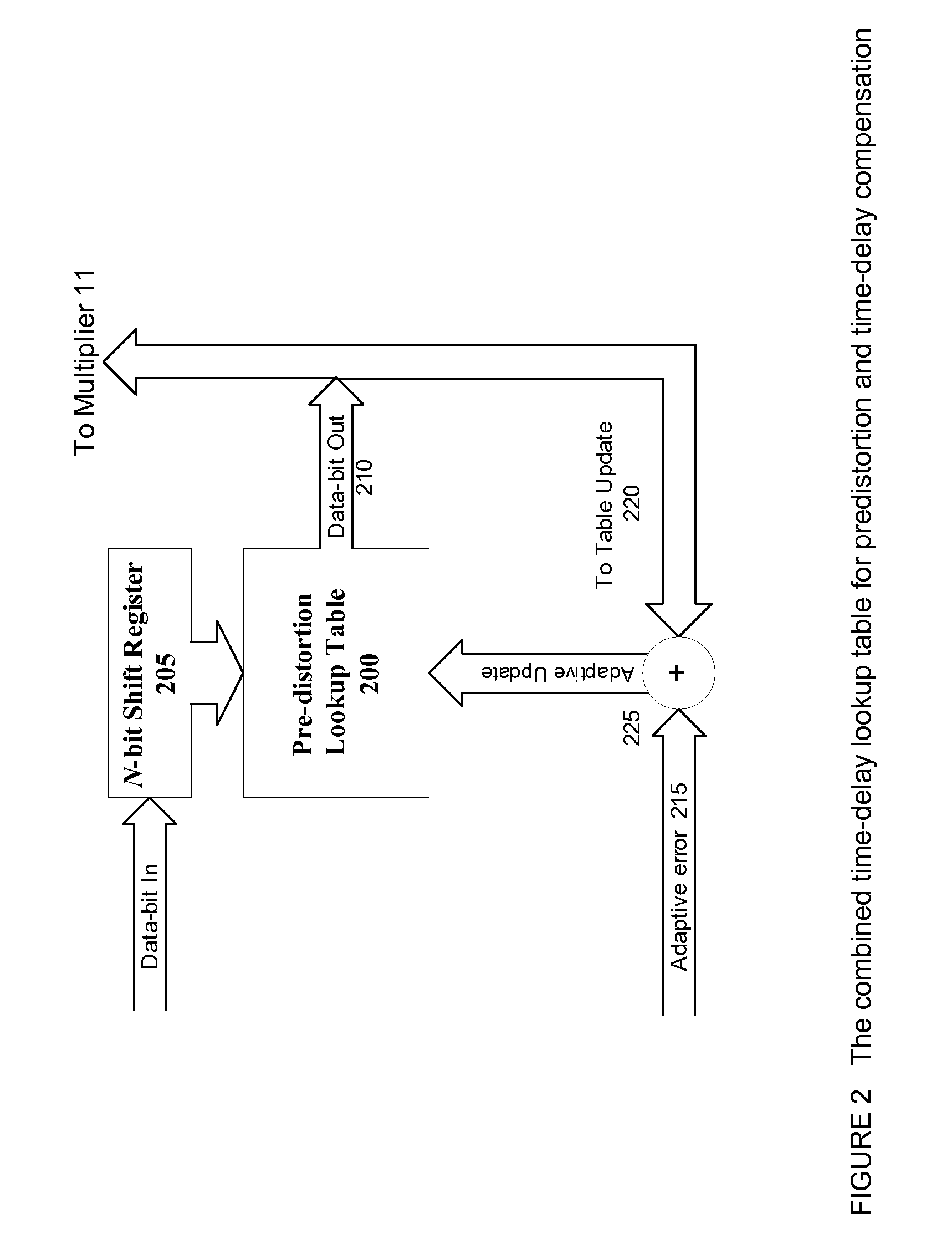
[0014]In one implementation of the invention, the entries for the lookup table are developed in accordance with the techniques described in pending U.S. patent application Ser. No. 11 / 262,079, filed Oct. 27, 2005, and U.S. patent application Ser. No. 11 / 799,239, filed Apr. 30, 2007, both of which are incorporated herein by reference. It will be appreciated by those skilled in the art that the range of errors which occur in a real-world system are bounded; that is, there is a range which has a minimum value and a maximum value, and in all but rare circumstances the correction factor applicable at the time of any given sample will fall within that range. By selecting a lookup table of appropriate size, and populating the lookup table with appropriate values as determined by the methods in the above-mentioned patent, which are selected over the entire operating spectrum of the PA and associated system, the correction factor which is appropriate for each sampling of the input signal wil...
PUM
 Abstract
Description
Claims
Application Information