Emergency location identification system

Active Publication Date: 2008-07-24
DEBAUGH CELEVATORON
View PDF7 Cites 6 Cited by
  • Summary
  • Abstract
  • Description
  • Claims
  • Application Information

AI Technical Summary

Benefits of technology

[0009]Still another objective of the invention is to provide a visual marker for emergency crews entering the home, which lights at the bedroom doors adding to increased safety for responding crews.
[0016]In other embodiment of the invention, the emergency location identification device is equipped with an external blue and green LED light panel. The notification light is mounted on an exterior wall above the house address numbers, that is activated whenever 911 is dialed. The purpose of the Blue Light is to reduce 911 emergency response times by allowing quick and accurate visual location identification by emergency response teams whether within a subdivision or out in the countryside.
[0017]The monitoring device is designed to be mounted close to the main phone junction box and plugged into the main electrical supply. The monitoring unit has a battery backup in case of power outages. The light casing is designed as a snub-nosed triangle with two blue panels facing outward at 45 degree angles to the street with a green panel that faces the street located between the blue light panels. The blue light panels allow the “flashing blue” to be seen as emergency crews approach the home. The flashing blue lights can be seen in almost all adverse weather conditions. Emergency response teams will be able to quickly find the location of the emergency even in a subdivision where all the homes look alike.
[0018]For homes out in the countryside where mailbox numbers and addresses are very difficult to find, the Blue Light provides easy-to-find location lighting in an emergency situation when time really counts. For extended driveways, there will be a Blue Light at the driveway / street intersection with extra lights running along the driveway to direct response teams to the home experiencing the emergency.
[0022]All lights may be white. Colors may be provided by a clip on lens cover. The lens cover is clear on top for easier location from the air.
[0034]The emergency location identification has advantages: (1) an emergency location identification system activates in a quick, convenient and efficient manner; (2) the system is easy to install; (3) the device saves time for the emergency crew to find the emergency sites; (4) the device can be plugged into the cigarette lighter / computer outlet in the car for signaling help for roadside emergencies; (5) the device can be used as a lighting post for visitors; (6) the device is operated easily by the users even at a non-emergency situations; (7) the device can displays predetermined visual information for communication between the user (host) and the guests.

Problems solved by technology

Everyone living on the earth is exposed to emergency situations like thefts, fires, injury accidents, natural disasters etc.
Still, residential crimes increase to an extent that a substantial number of households end up renting a household emergency alert system.
In many cases, however, it is challenging, especially in a metropolitan area, for the emergency crew to locate the scene where the victims of the emergency need desperate help.
The street clogs down by cars in the first place.
Even though the emergency crews got close to the scene, now it is hard to find the exact location of the emergency site.
With all these myriads of obstacles, pinpointing the right location of emergency is not easy no matter how imminent the situations are.

Method used


Image

  • Emergency location identification system
  • Emergency location identification system
  • Emergency location identification system

Examples


Embodiment Construction

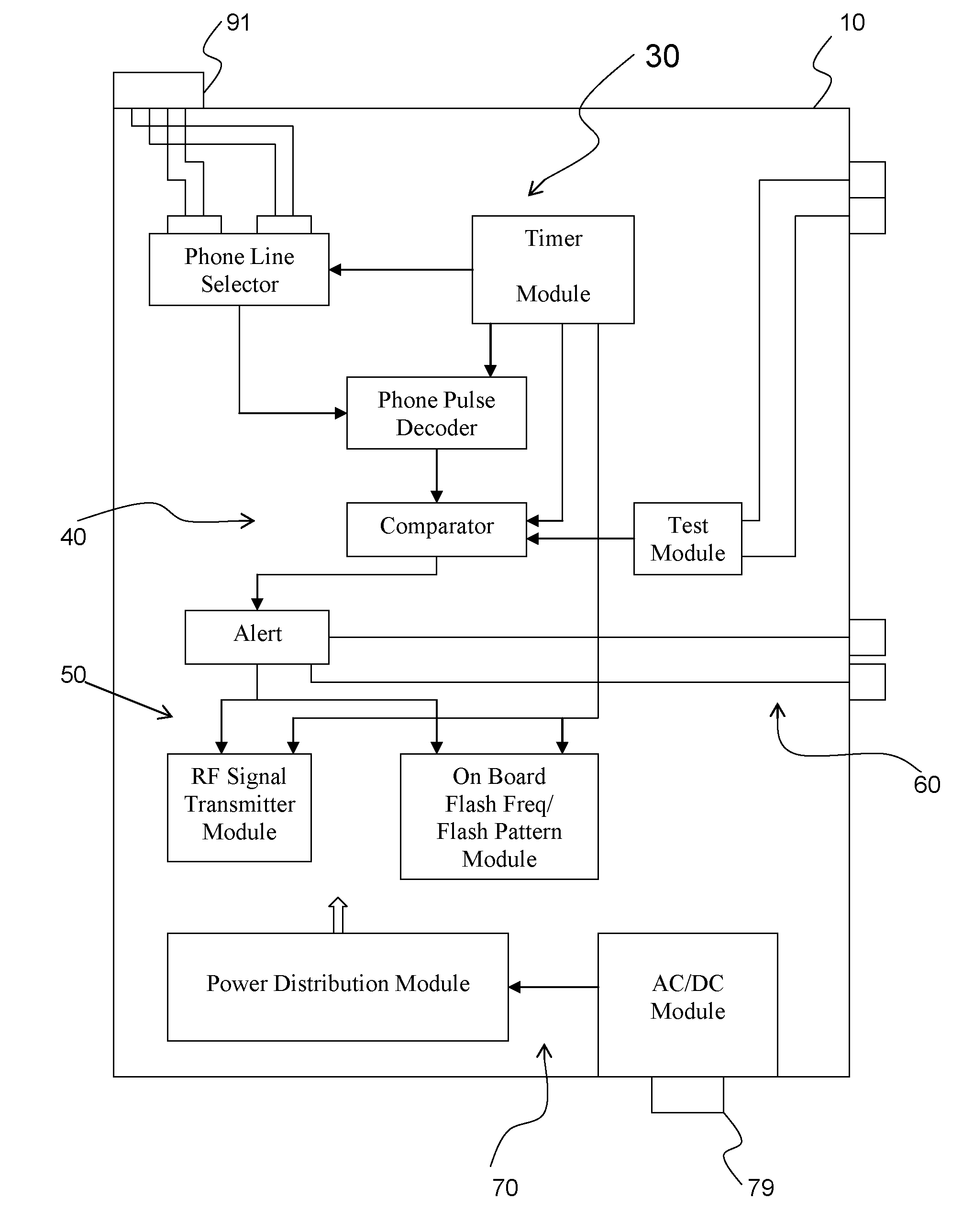
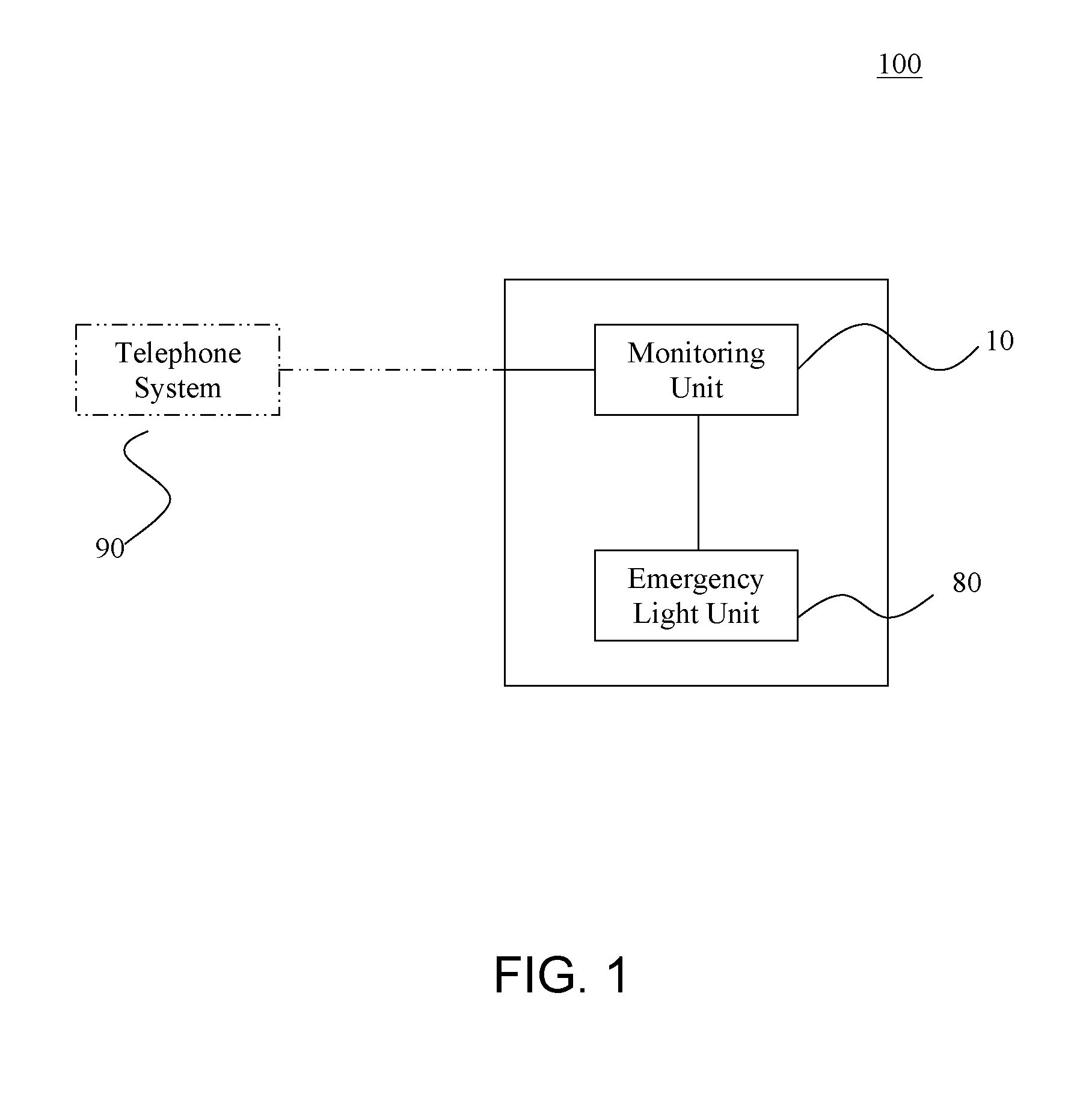
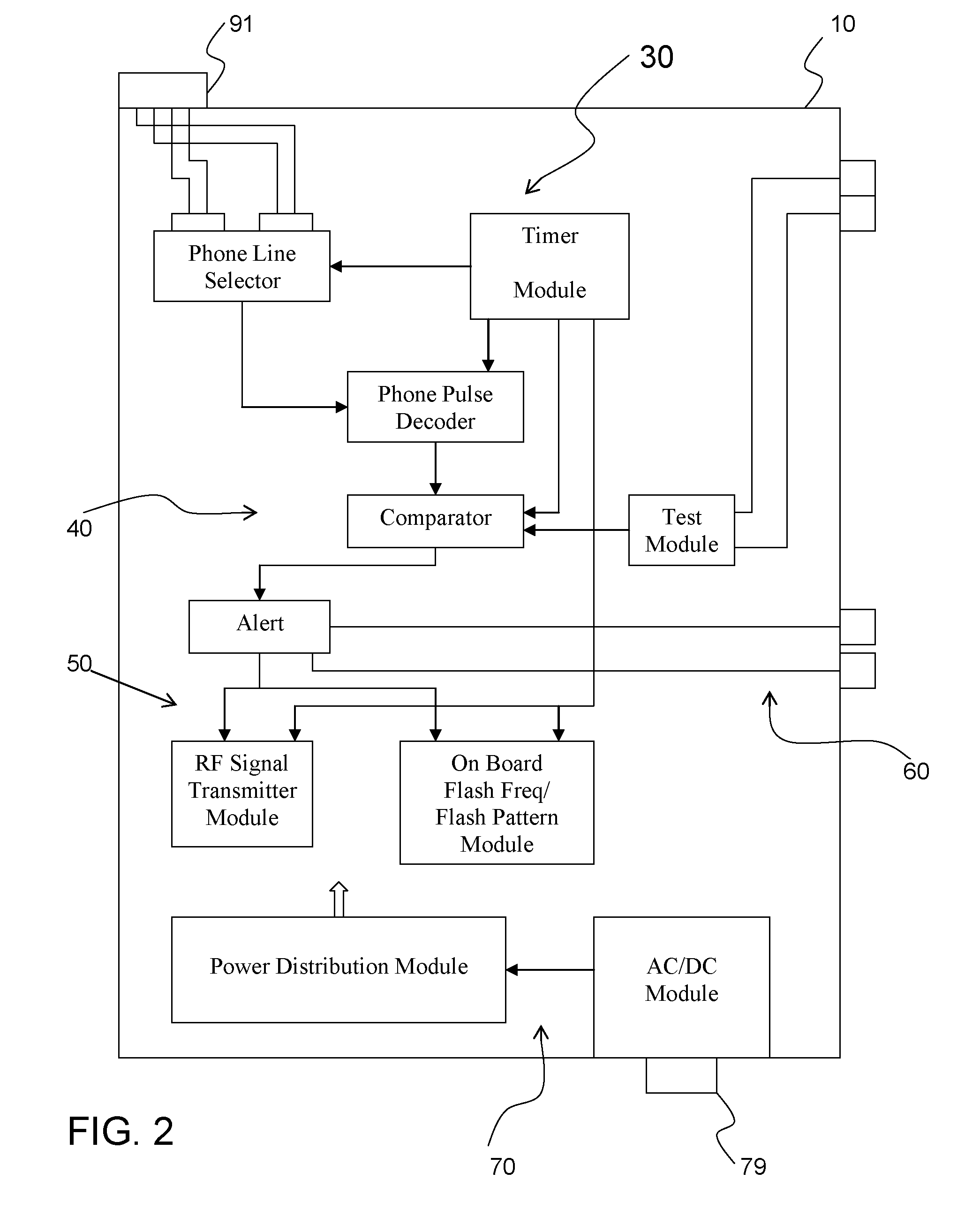
[0046]FIG. 1 shows a schematic block diagram illustrating an emergency location identification system 100 connected to a telephone system 90 according to the present invention. The emergency location identification system 100 associated with a telephone system 90 comprises the monitoring unit 10 and the emergency light unit 80.

[0047]The monitoring unit 10 is configured to be connected to the telephone system 90 for generating signals by monitoring phone calls made at the telephone system 90. The emergency light unit 80 is controlled by the signals from the monitoring unit 10. The emergency light unit 80 comprises one or more first light panels 81 and a plurality of second light panels 82 as shown in FIG. 8, and the light panels 81, 82 are disposed at a plurality of locations around a facility 92 in which the telephone system 90 is located as shown in FIG. 9.

[0048]The emergency light unit 80 is activated when an emergency call is made at the telephone system 90, and the emergency lig...


PUM


Abstract

An emergency location identification system is provided. The system includes a monitoring unit and an emergency light unit. The monitoring unit is connected to a telephone system of a facility, and responds to some predetermined dialing of the telephone generating signals, which is going to control the behavior of the emergency light unit. The emergency light unit includes a plurality of colors and shapes adapted to display a emergency location identification to an emergency crew or visitors. The emergency light unit may include blue, green, and red lights and may flash for some instances. Also, the emergency light may have a predetermined shape such as arrow, triangle, and others to alert people properly for the emergency situations.

Description

BACKGROUND OF THE INVENTION[0001]The present invention relates to an emergency alert device and, more particularly, to an improved emergency alert system enabling emergency location identification in a quick, convenient and efficient manner.[0002]An emergency takes place without regard to precautions. Everyone living on the earth is exposed to emergency situations like thefts, fires, injury accidents, natural disasters etc. Urgent medical attention is critical on the scene of emergency to cope with such incidents so that a number of precautionary measures have been introduced. Alarm systems for earthquake, hurricane and flood have been around for years. Fire alarm system is one of the old skills we developed and still use. Still, residential crimes increase to an extent that a substantial number of households end up renting a household emergency alert system.[0003]The most known emergency system includes a 911 service. An emergency is reported through a centralized communication net...

Claims


Application Information

Patent Timeline
IPC IPC(8): H04M11/04
CPCG08B25/08G08B7/064
Inventor DEBAUGH, CLIFTON
Owner DEBAUGH CELEVATORON
Why Eureka
Try Eureka