
Processing chamber with heated chamber liner

Active Publication Date: 2008-07-31
APPLIED MATERIALS INC
View PDF25 Cites 141 Cited by
  • Summary
  • Abstract
  • Description
  • Claims
  • Application Information

AI Technical Summary

Benefits of technology

[0011]In some embodiments, a liner assembly for a processing chamber can include a ceramic body having an inner diameter surface bounding a portion of a pumping cavity. A pumping aperture is disposed through the body and fluidly couples to the pumping cavity through the inner diameter surface. A heating element is embedded in the body. A flange extending outward from an outer diameter of the body and has an upper surface. A portion of the upper surface of the flange has a sealing surface. At least one pad extends from the upper surface of the flange to an elevation beyond the sealing surface. At least one thermal choke is defined in the flange. A recess is formed in the upper surface between the sealing surface and the pad. The pad, choke and recess contribute to control of the temperature of the liner assembly.

Problems solved by technology

One problem that has been encountered during plasma processing is the non-uniform temperature distribution in the processing chamber during processing.
For example, in a processing chamber body having two plasma processing regions separated by a shared internal wall, the internal wall is heated from the plasma from both regions while the external walls are heated by only one of the plasmas, thereby creating an unbalanced heat load which results in the exterior walls having a lower temperature relative to the internal wall.
The low temperature may cause process gases or precursors to condense on the wall surfaces having the reduced temperature, thereby resulting in particle generation that may lead to contamination of the deposited film.
Particles generation within the chamber may also accumulate in and eventually obstruct the pumping port, thereby requiring an interruption in processing to clear the pumping port.
Additionally, particles within the chamber may compromise chamber seals, thereby resulting in thermal energy loss and further aggravating the temperature uniformity of chamber walls.

Method used


Image

  • Processing chamber with heated chamber liner
  • Processing chamber with heated chamber liner
  • Processing chamber with heated chamber liner

Examples


Embodiment Construction

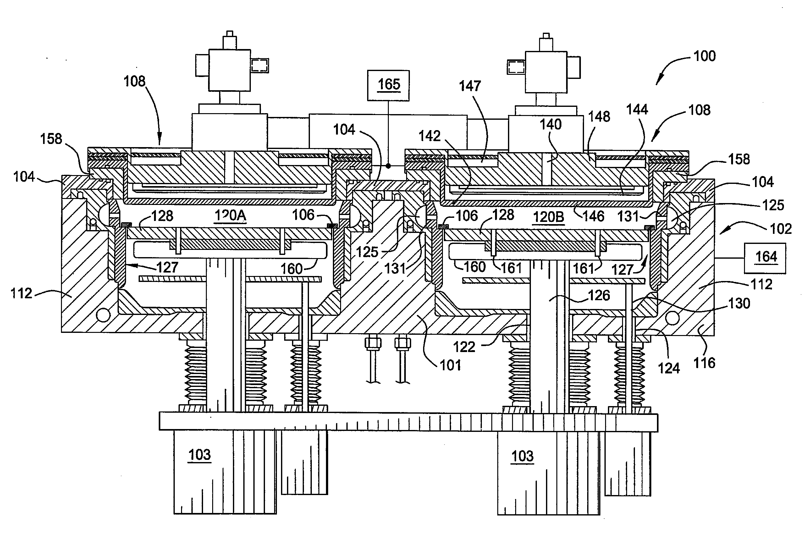
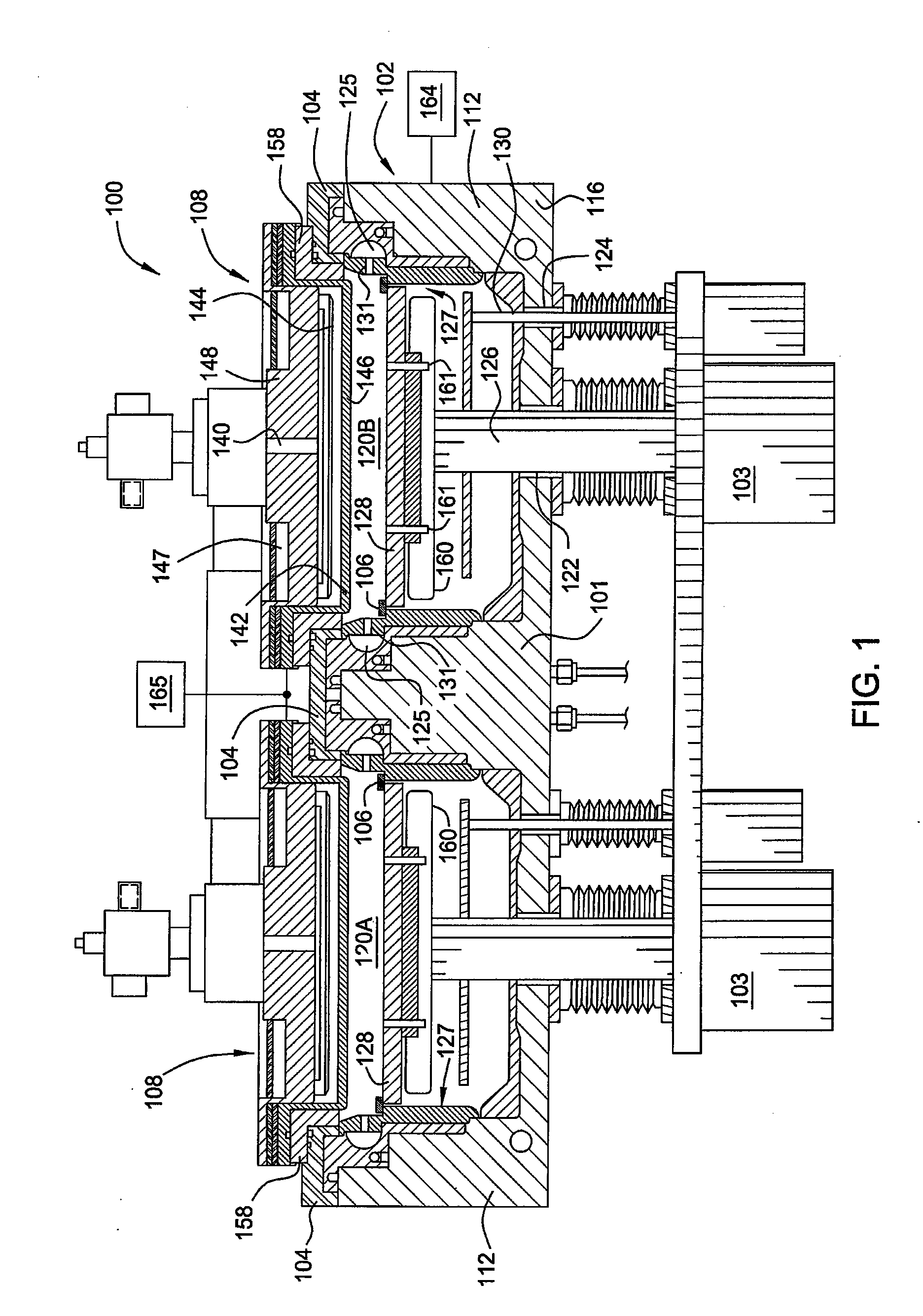
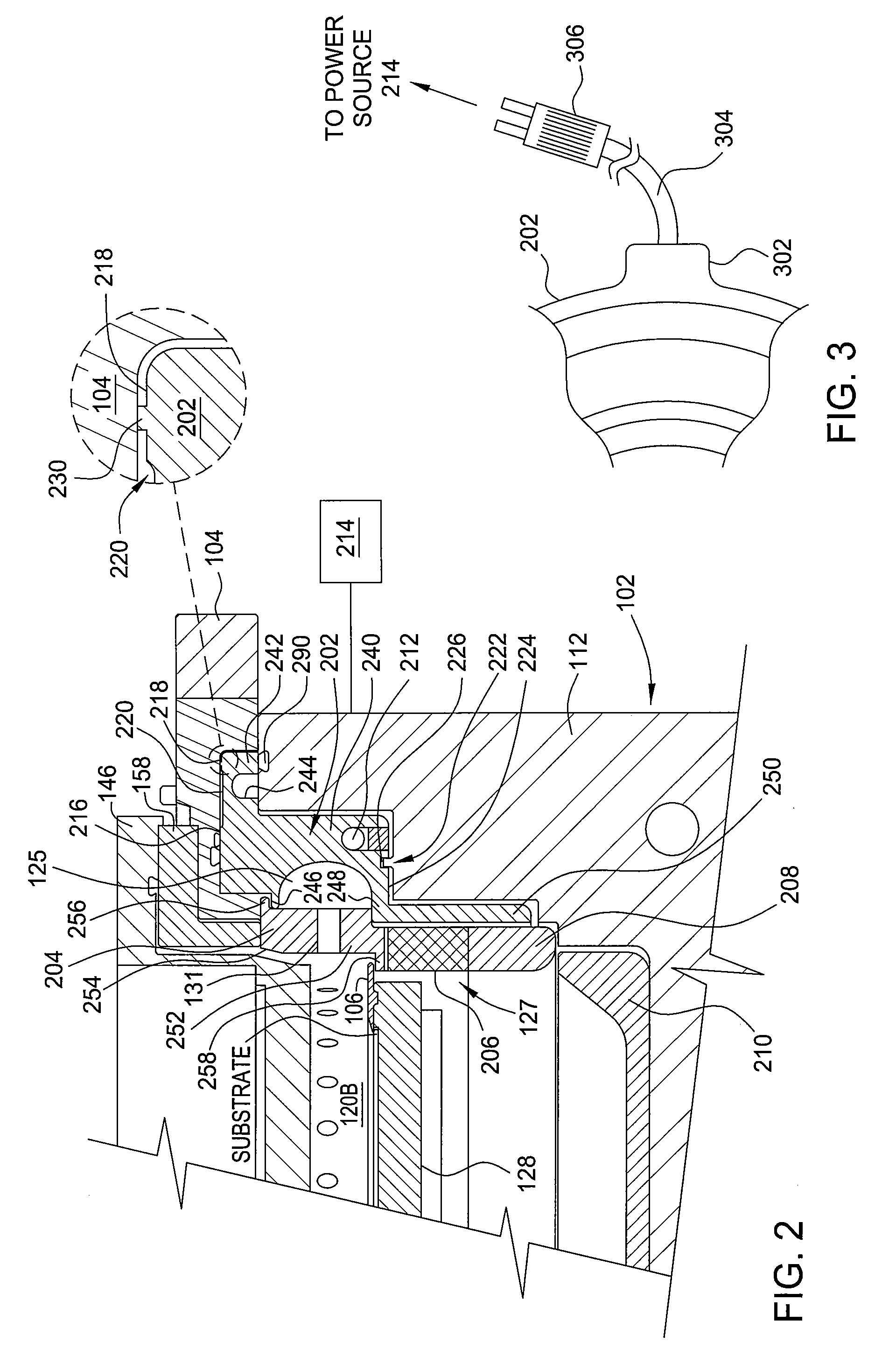
[0023]The liner assembly of the present invention advantageously minimizes heat transfer between the chamber body and the liner assembly. In some embodiments, the liner assembly may be configured to compensate for non-uniform heating of the liner assembly such that the temperature of the liner assembly may be maintained with at a uniform or non-uniform profile.

[0024]Embodiments of the present invention are illustratively described below in reference plasma enhanced chemical vapor deposition (PECVD) system. Examples of PECVD systems that may be adapted to benefit from the invention include a PRODUCER® SE CVD system or a DXZ® CVD system, both commercially available from Applied Materials, Inc., Santa Clara, Calif. The Producer® SE CVD system (e.g., 200 mm or 300 mm) has two isolated processing regions that may be used to deposit carbon-doped silicon oxides and other materials and is described in U.S. Pat. Nos. 5,855,681 and 6,495,233, both of which are incorporated by reference. The D...


PUM

PropertyMeasurementUnit
Temperatureaaaaaaaaaa
Diameteraaaaaaaaaa
Heataaaaaaaaaa

Abstract

A heater liner assembly suitable for covering the interior of a plasma processing chamber is provided. In some embodiments, a liner assembly for a processing chamber can include a heating element embedded in a body. A flange extending outward from an outer diameter of the body includes an upper surface having a sealing surface and at least one pad that extends from the upper surface of the flange to an elevation beyond the sealing surface. The pad contributes to control of the temperature of the liner assembly by maintaining the liner assembly spaced apart from the processing chamber.

Description

BACKGROUND OF THE INVENTION[0001]1. Field of the Invention[0002]Embodiments of the invention generally relate to a semiconductor processing chamber and, more specifically, a liner assembly used in a semiconductor processing chamber.[0003]2. Description of the Related Art[0004]Semiconductor processing involves a number of different chemical and physical processes whereby minute integrated circuits are created on a substrate. Layers of materials which make up the integrated circuit are created by chemical vapor deposition, physical vapor deposition, epitaxial growth, and the like. Some of the layers of material are patterned using photoresist masks and wet or dry etching techniques. The substrate utilized to form integrated circuits may be silicon, gallium arsenide, indium phosphide, glass, or other appropriate material.[0005]In the manufacture of integrated circuits, plasma processes are often used for deposition or etching of various material layers. Plasma processing offers many ad...

Claims


Application Information

Patent Timeline
IPC IPC(8): B05C11/00
CPCC23C16/46C23C16/4405C23C16/4409
Inventor FODOR, MARK A.VELASTEGUI, SOPHIA M.KIM, BOK HOENDUBOIS, DALE R.
Owner APPLIED MATERIALS INC
Features
  • Generate Ideas
  • Intellectual Property
  • Life Sciences
  • Materials
  • Tech Scout
  • Unparalleled Data Quality
  • Higher Quality Content
  • 60% Fewer Hallucinations
Learn More