Coker feed method and apparatus

a feed method and coke technology, applied in the field of delayed coke, can solve the problems of uniform heat distribution, operator exposure to steam, serious injuries and fatalities, etc., and achieve the effects of reducing the total thermal stress, and being more controllable and predictabl

Inactive Publication Date: 2008-07-31
EXXON RES & ENG CO
View PDF17 Cites 74 Cited by
  • Summary
  • Abstract
  • Description
  • Claims
  • Application Information

AI Technical Summary

Benefits of technology

[0021]Described herein are methods and mechanisms for laterally dispensing fluid to a coke drum in a predictable and maintainable manner that reduces drum/vessel thermal stress. The methods and mechanisms utilize a split piping system to dispense fluid through two or more inlets into a spool that is connected to a coke drum. The use of a combination of block valves and clean out ports provides an effective means to clean the lines and, thereby, allows the fluid to be laterally dispensed in a more controllable and predictable manner. The fluid may be introduced to the spool in opposing directions toward a central vertical axis of the spool at any angle between minus 30 degrees and 30 degrees relative to horizontal or, less p

Problems solved by technology

Manually removing the heads, especially the bottom heads, is dangerous work and has resulted in serious injuries and fatalities.
Operators face significant risk of injury from exposure to steam, hot water, coke fallout, fire, etc.
The thermal shock caused by this non-uniform heat distribution expresses itself in a number of ways, including: recurrent plastic deformation of the coke drum bottom and eventual ovalization; leaks in nearby gasketed joints; metal fatigue; and cracks in the drum.

Method used


Image

  • Coker feed method and apparatus
  • Coker feed method and apparatus
  • Coker feed method and apparatus

Examples


example 1

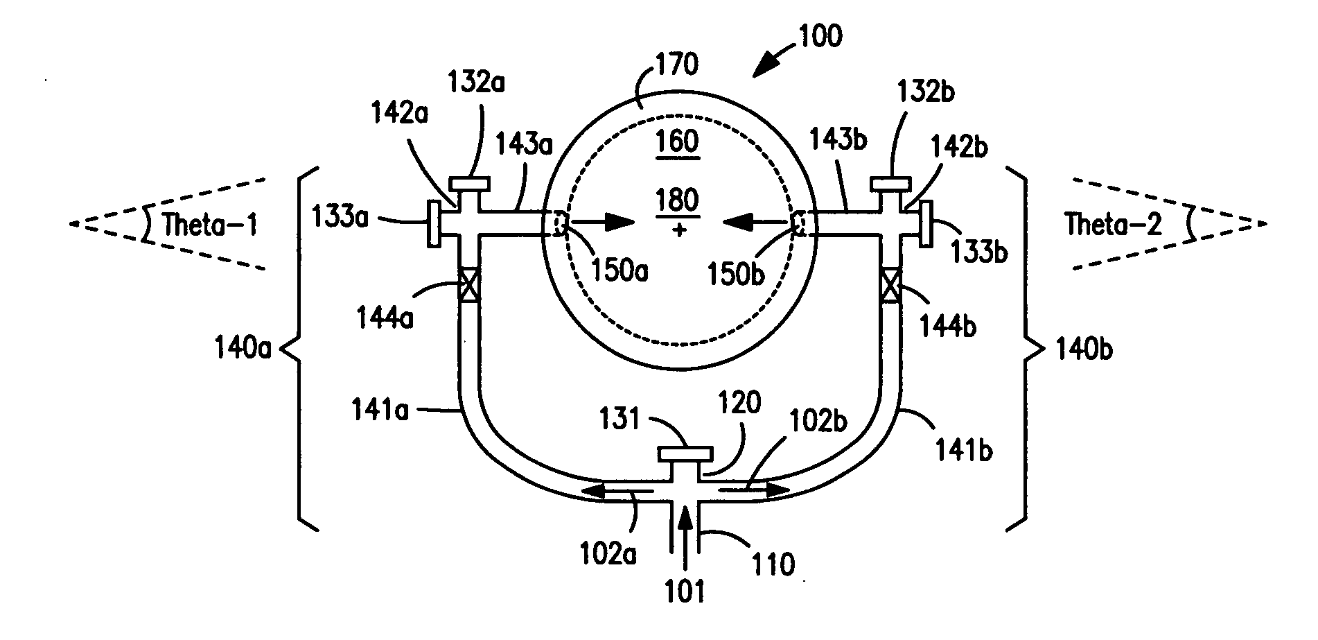
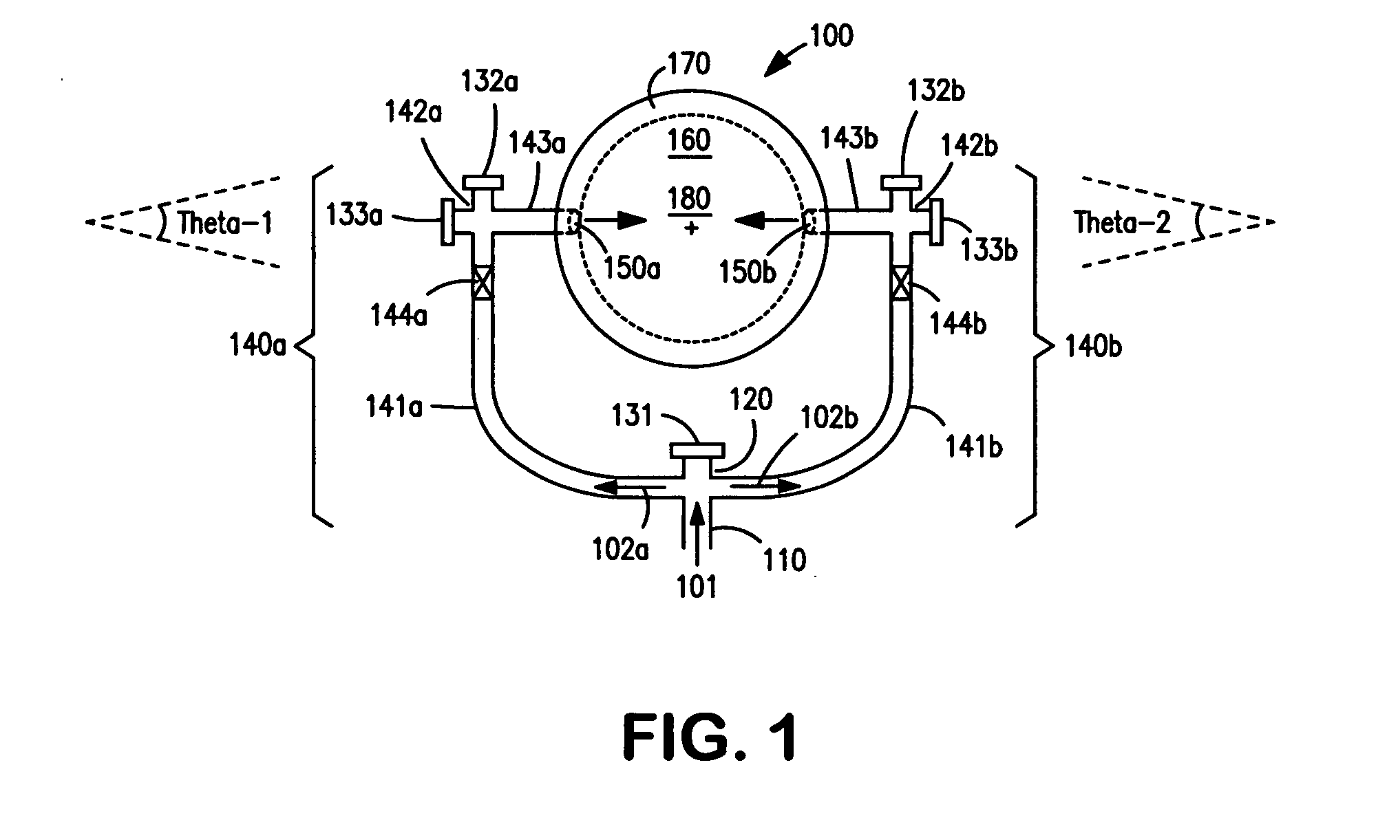
[0071]An existing coke drum has a 72″ diameter bottom manway, and an 8″ diameter feed line which enters the existing bottom head vertically on the center axis of the coke drum. It is desired to employ a nominal 60″ diameter Zimmermann & Jansen or DeltaValve coke drum bottom deheader valve on this installation.

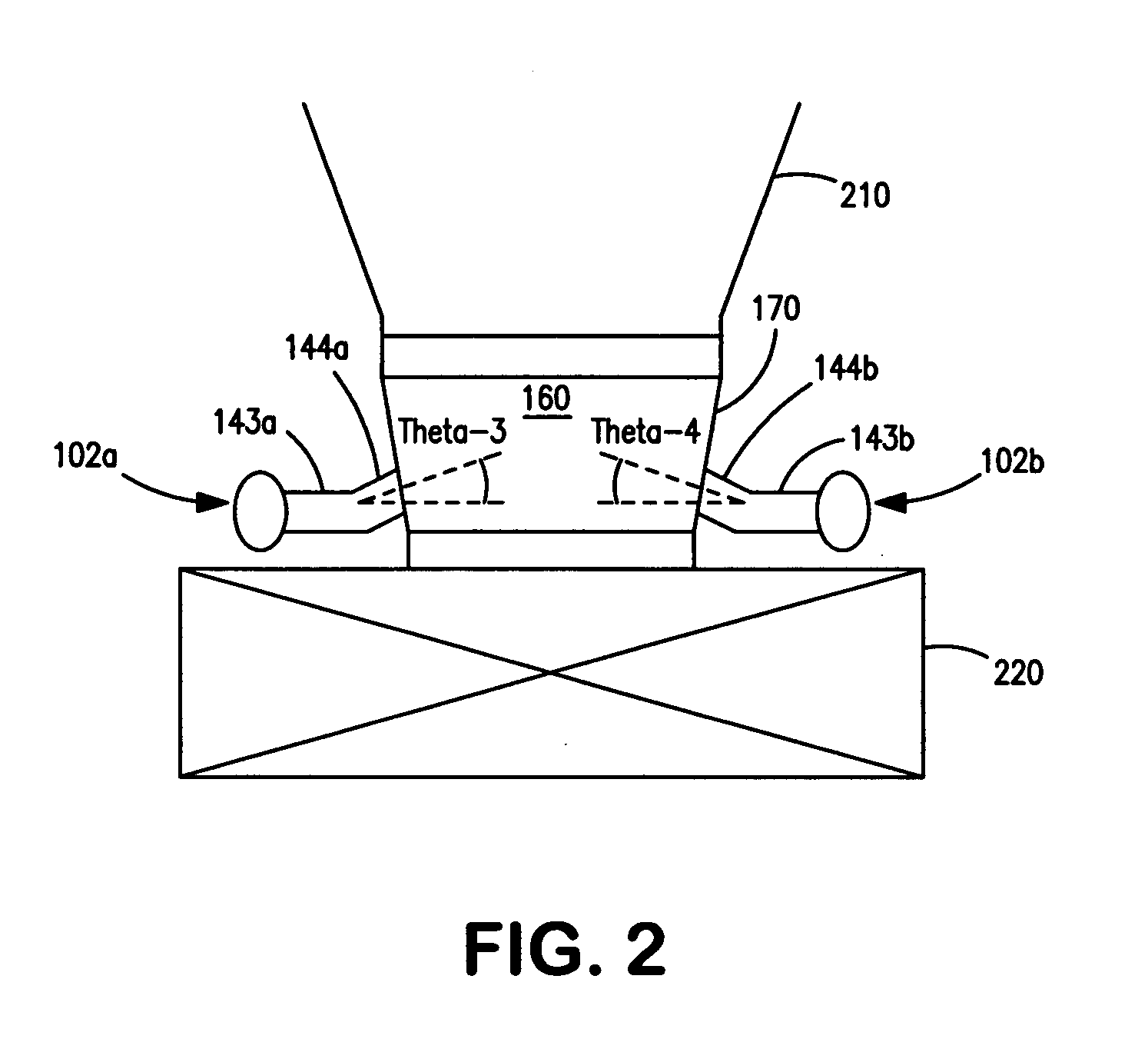
[0072]A flanged 72″×60″ transition cone / spool is fabricated. The cone is fabricated from 1 Chrome ½ Moly steel and has a ⅛″ thick 410 stainless steel interior overlay. Two 6″ 9-chrome nozzles are located 180 degrees apart on the cone, and are as low to the bottom of the cone as allowed by mechanical design code. The angles that the nozzles make, relative to horizontal, are set so that if flow from the nozzle were to impinge on the opposing wall it would not impinge directly on the upper flange. In this instance, the cone is 32″ high, has a lower opening with a 60″ diameter and an upper opening with a 72″ diameter and the nozzle angles are equal and set at 5 degrees above horizo...

example 2

[0081]The system above is equipped with 28 thermocouples strategically located on the feed inlet lines, coke drum cone and coke drum valve. Temperature signals are obtained throughout the coking cycles. The temperature signals are digitized and used as inputs to automatic controllers which control the rate of the quench water so as to optimize throughput and, thereby, minimize stress on the inlet components, drum cone, and bottom valve. The temperature data also provide indices of equipment health.

example 3

[0082]In the system above, steam is added to the inlet piping during the coke drum emptying cycle to help “aerate” the coke plus water mixture exiting from the coke drum and, thereby, help control the flow rate of the coke plus water mixture.


PUM


Abstract

Described herein are methods and mechanisms for laterally dispensing fluid to a coke drum in a predictable and maintainable manner that alleviates thermal stress. In one embodiment, the methods and mechanisms utilize a split piping system to dispense fluid through two or more inlets into a spool that is connected to a coke drum and a coke drum bottom deheader valve. A combination of block valves and clean out ports provides a more effective means to clean the lines and allows fluid to be laterally dispensed in a controllable and predictable manner. The fluid is preferably introduced to the spool in opposing directions toward a central vertical axis of the spool at equal but opposing angles ranging from minus thirty (−30) to thirty (30) degrees relative to a horizontal line laterally bisecting the spool. Alternatively, however, fluid can be introduced to the spool tangentially.

Description

1.0 CROSS REFERENCE TO RELATED APPLICATION[0001]This invention relates and claims priority to U.S. Provisional Patent Application No. 60 / 897,242, filed on Jan. 25, 2007, entitled “Coker Feed Method And Apparatus”.2.0 BACKGROUND OF THE INVENTION[0002]2.1 Field[0003]The field of the invention is delayed coking. More particularly, the field of the invention is methods and mechanisms for dispensing fluid to delayed coke drums.[0004]2.2 Description of Related Art[0005]In delayed coking, heavy distillation fractions (“resid” or “residuum”) is typically heated rapidly in a fired heater or tubular furnace to create a mixture of hot liquid and vapor which is then fed to a large steel vessel commonly known as a coke drum. The coke drum is maintained under conditions in which coking occurs (e.g., greater than about 400° C. under super-atmospheric pressures). Delayed coke drums are typically cylindrical vessels with a cone at the bottom; that range in diameter anywhere from about 15 to 30 feet....

Claims


Application Information

Patent Timeline
IPC IPC(8): B01D1/00
CPCC10B1/04C10B55/00C10B31/12
Inventor CHEN, TE-HUNGEPPIG, CHRISTOPHER P.HEALY, TIMOTHY M.MASSENZIO, SCOTT F.MOSLEY, ROBERT W.PATEL, RUTTON D.
Owner EXXON RES & ENG CO
Why Eureka
Try Eureka