Coatings for use in fuel injector components

Inactive Publication Date: 2008-07-31
CATERPILLAR INC
View PDF47 Cites 3 Cited by
  • Summary
  • Abstract
  • Description
  • Claims
  • Application Information

AI Technical Summary

Benefits of technology

[0015]A further aspect of the invention is that the disclosed coatings or surface treatments of the fuel system component operate to augment the lubricity of certain low lubricity fuels. The disclosed coatings applied to the fuel injector plunger and the corresponding mating component (e.g. fuel injector barrel) can significantly reduce the possibility of lubricity related failures of the fuel injector. Utilization of such coatings on fuel injector system components can reduce or eliminate the need for adding lubricants to the low lubricity fuel compositions.

Problems solved by technology

Additionally, the hydraulically actuated electronically controlled unit injector often operates at a more severe condition than the mechanically actuated electronically controlled unit injector.
The decreased surface area in which to spread out the contact stress causes the hydraulically actuated electronically controlled unit injector to experience increased wear at the contact surfaces relative to mechanically actuated electronically controlled unit injectors, which have considerably longer engaged length between the fuel injector plunger and the mating barrel.
The use of low lubricity fuels, in particular, can cause several problems, most notably fuel injector plunger scuffing, and ultimately the seizure of the fuel injector plunger within the bore of the fuel injector.
Scuffing is typically caused by lack of lubrication at the interface between two hard surfaces causing a welding or adhesion of the contacting parts, e.g. fuel injector plunger and fuel injector barrel sliding against one another without proper lubrication tend to show evidence of scuffing.
Scuffing, which is a form of wear, will change the clearance between the plunger and the barrel and will make the surface rough so the sliding motion of the plunger will not be smooth, both of which will lead to an incorrect amount of fuel injected into the system.
Eventually, continued scuffing can lead to seizure of the fuel injector plunger in the barrel as the plunger and barrel will effectively merge into one part with no movement allowed.
The aforementioned problems exist primarily, although not exclusively with low lubricity fuels and other non-standard fuels including gasoline, naphtha, D1 type diesel fuels, aviation fuels, blended or heavy fuels, crude oils or water / fuel emulsions, including water continuous and fuel continuous emulsions.
The problem encountered with TiN coatings is that a TiN coating is usually applied at extremely high temperatures (e.g. about 450 degrees C.) which may produce unwanted thermal stresses and related failures to the fuel injector plunger.
It is also believed that TiN coatings on fuel injector plungers tend to increase the wear of the plunger mating component at the mating or seating location.
In addition, TiN coatings tend to increase the overall cost of the fuel injector plunger because the TiN coated fuel injector plunger requires tool grade steel to withstand the high temperatures observed in the application of the TiN coating.
Unfortunately, the use of a ceramic material for fuel injector plungers is very costly and the resulting monolithic ceramic fuel injector plungers have not typically demonstrated the necessary durability or reliability for commercial use in diesel engines or other heavy duty engine applications.

Method used


Image

  • Coatings for use in fuel injector components
  • Coatings for use in fuel injector components
  • Coatings for use in fuel injector components

Examples


examples

[0055]The following Examples will serve to further typify the nature of the invention but should not be construed as a limitation on the scope thereof.

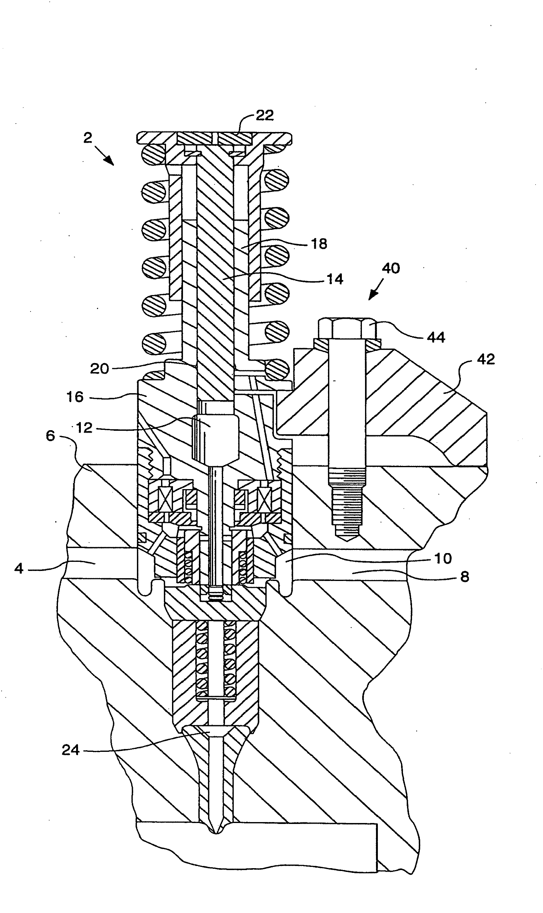
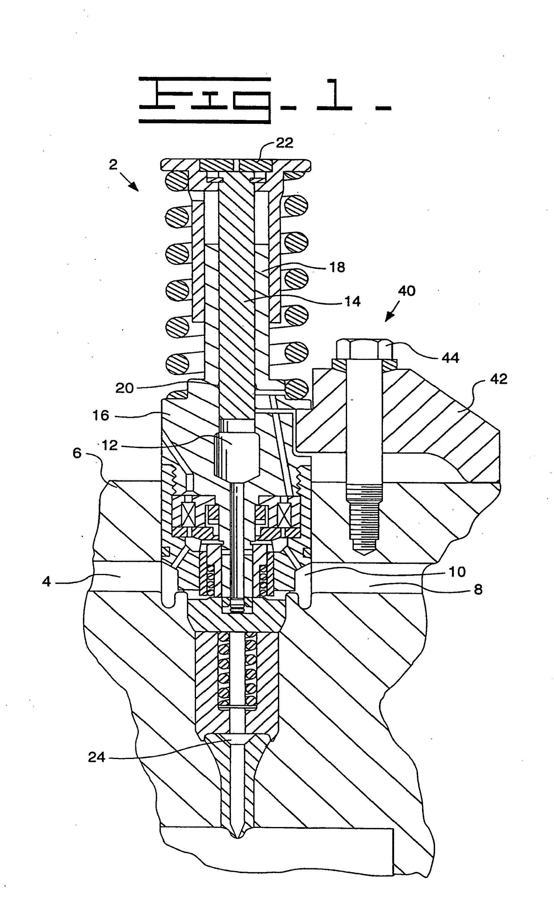
[0056]Accelerated scuffing and seizure tests were performed on a Caterpillar fuel injector plunger operating within a Caterpillar Fuel Injector. The fuel injector plungers included at least one with a chromium nitride coating and at least one having a tungsten carbide containing carbon coating and were compared to scuffing and seizure tests for a baseline Caterpillar fuel injector plunger having no coating. The Caterpillar Fuel Injectors were testing using direct injection of a low lubricity fuel and direct injection of water.

[0057]The fuel used was Caterpillar fuel 1E2820, which is a low lubricity diesel fuel. 18 plungers were utilized per test. The plunger part number used was #1124312, and the injector part number was #146-1891. The plungers were tested for three hours.

[0058]An additional performance test, ET213, was completed on 6...


PUM

PropertyMeasurementUnit
Timeaaaaaaaaaa
Thicknessaaaaaaaaaa
Thicknessaaaaaaaaaa

Abstract

A coating for fuel injector components adapted for use with low lubricity fuels is disclosed. The invention consists of a metal carbon material coating or a metal nitride coating to the fuel pump plunger or other fuel injection system components. The invention utilizes a coating on the fuel injector plunger that minimizes scuffing or seizure associated with the plunger and barrel.

Description

[0001]This application claims the benefit of prior provisional patent application Ser. No. 60 / 101,382 filed Sep. 21, 1998.FIELD OF THE INVENTION[0002]The present invention relates to fuel injectors and more particularly to coatings or surface treatments for fuel injector components such as fuel injector plungers.BACKGROUND OF THE INVENTION[0003]Many internal combustion engines, whether compression ignition or spark ignition engines, are provided with fuel injection systems to satisfy the need for precise and reliable fuel delivery into the combustion chamber of the engine. Such precision and reliability is necessary to address the goals of increasing fuel efficiency, maximizing power output, and controlling undesirable by-products of combustion.[0004]A fuel injector is a precision device that must meter the quantity of fuel required for each cycle of the engine and must develop the high pressure necessary to inject the fuel into the combustion chamber at the correct instant of the o...

Claims


Application Information

Patent Timeline
IPC IPC(8): B05B1/00C23C14/02F02M61/16C23C14/06C23C16/02C23C16/26F02M59/44
CPCC23C14/025C23C14/0611C23C14/0635F02M59/445C23C14/0664C23C16/0281F02M59/44C23C14/0641Y10S239/19Y10T137/7036
Inventor CAMPION, ROBERT M.DAM, CHUONG Q.HALL, KENNETH W.RODIER, WILLIAM J.
Owner CATERPILLAR INC
Why Eureka
Try Eureka