Process for atomic layer deposition

a technology of atomic layer and deposition method, which is applied in the direction of chemical vapor deposition coating, coating, additive manufacturing apparatus, etc., can solve the problems of poor subthreshold slope and high current, and achieve excellent field-effect electron mobilities and sufficient performance properties

Active Publication Date: 2008-07-31
EASTMAN KODAK CO
View PDF9 Cites 4030 Cited by
  • Summary
  • Abstract
  • Description
  • Claims
  • Application Information

AI Technical Summary

Benefits of technology

[0055]It is an advantage of the present invention that it provides an advantageous process for atomic layer deposition of a zinc-oxide-based n-type semiconductor onto a substrate, well suited to a number of different types of substrates and deposition environments.
[0056]It is yet a further advantage of the present invention that it is adaptable for deposition on a web or other moving substrate, including deposition onto a large area substrate.
[0057]It is a further advantage of the present invention that it allows operation, in preferred embodiments, under atmospheric pressure conditions.
[0058]It is still a further advantage of the present invention tha...

Problems solved by technology
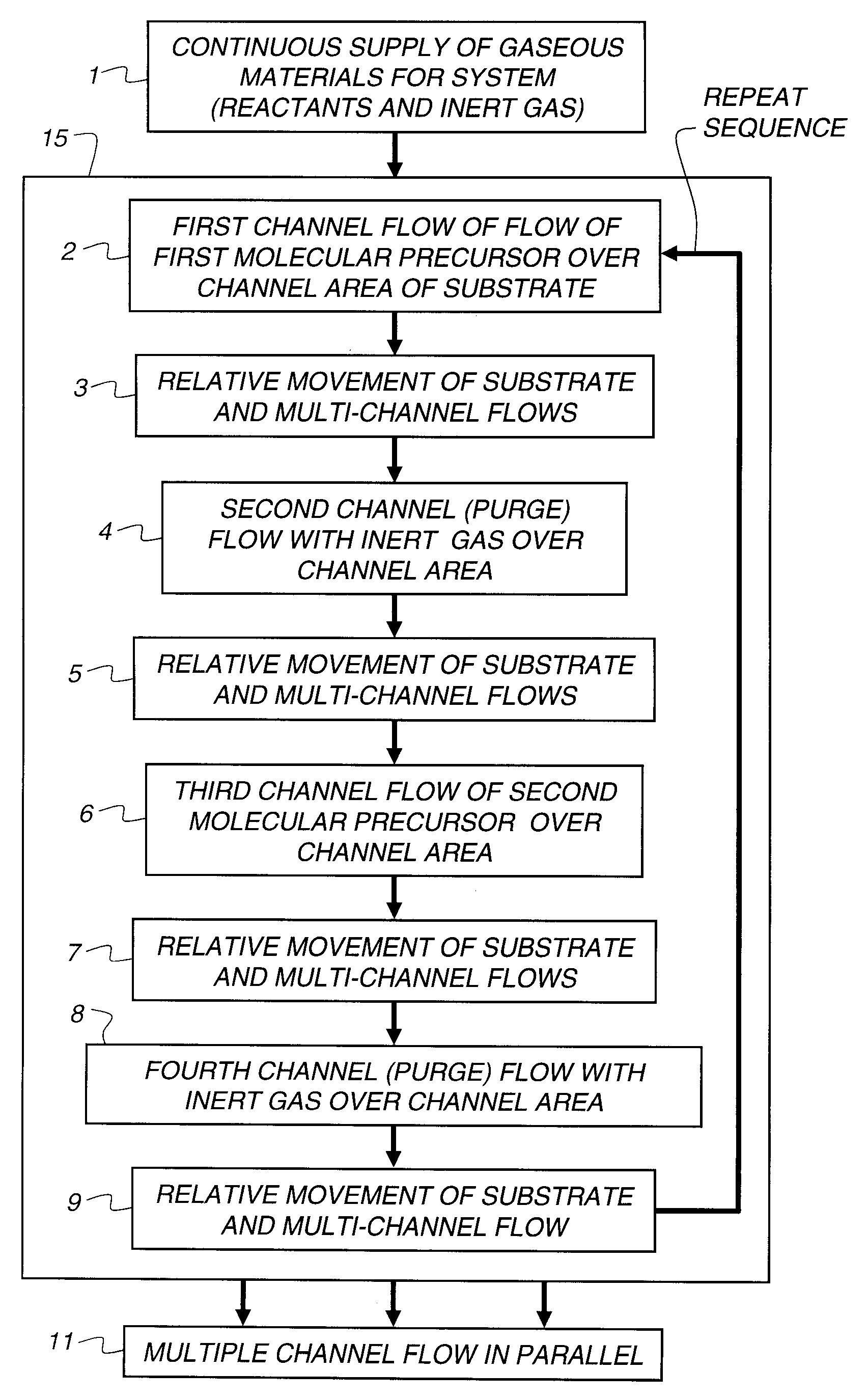
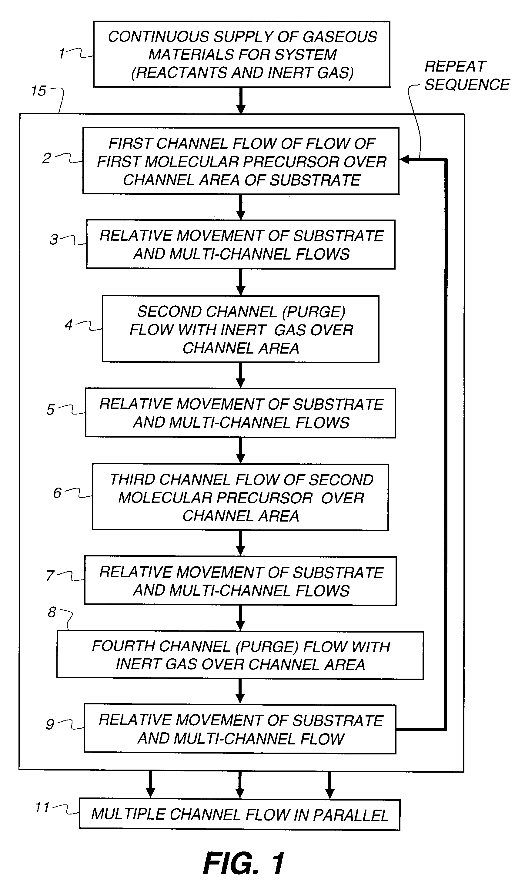
In the material produced by a spatial ALD process, defects in the materials lead to two deleterious effects.
First of all, such materials tend to have too high a concentrat...

Method used


Image

  • Process for atomic layer deposition
  • Process for atomic layer deposition
  • Process for atomic layer deposition

Examples


example 2

Preparation of Nitrogen-Doped ZnO Semiconductor Layer Using Atmospheric Pressure ALD Process

[0222]The preparation of the nitrogen-doped ZnO layer in this example is identical to that in Example 1 except that the pure water in the bubbler in that example is replaced by a solution of ammonia in water, at the concentration specified in Table 1 below.

TABLE 1N2 withN2Ammonia / MetalwithN2 InertSampleLayerMe3Al*Et2Zn*WaterWater**Air*AlkylAirPurgeCyclesAAl2O380804.8620110015003001ZnO 200 Å06804.8620110015001602N-Doped06084.862011001500160ZnO 200 Å*Flow values in sccm (standard cubic centimeters / min)**15% NH3 by weight in water

[0223]Aluminum source and drain contacts were evaporated on the resulting multilayer device through a shadow mask, yielding thin film transistors with a channel length of 50, 100 or 150 μm and a channel width of 500 μm. A photolithographic process was used to isolate devices on the substrate, producing islands of ZnO. Electrical test results for the above devices are sh...

example 3

[0224]This example describes the preparation of devices made using a range of NH3 concentrations in water. This experiment is similar to that described in example 1 except that the concentration of ammonia in the water bubbler solution was varied from 0 to 29 weight percent. The ammonia concentration used varied as in Table 3.

TABLE 3Ammonia ConcentrationSampleweight % in water3A03B0.733C3.63D29

TABLE 4AverageSubthresholdAverageSampleMobilitySlopeIon / Ioff3A5.433.141.9 × 1063B6.471.358.1 × 1073C7.421.415.3 × 1073D4.171.032.3 × 108

[0225]The data in Table 4 above show that the higher levels of ammonia during the ZnO deposition have a substantial improvement in on / off ratio. The experiment also showed that the higher levels of ammonia during the ZnO deposition have a substantial improvement in subthreshold slope and mobility as the concentration of ammonia was increased up to a point and then it appeared to drop (for mobility only) at the highest ammonia concentration.

example 4

[0226]The purpose of this example is to demonstrate that by using N-doping in ZnO layers that it is possible to prepare TFTs that have a broad range of useful electrical properties. The samples were prepared in a fashion identical to that in Example 2, Sample 2 except that the number of cycles that the coating head made (hence the thickness of the ZnO layer) was varied from 50 to 200 (63 to 250 Angstroms thick. All samples in this example were prepared with 14.5 weight % ammonia in the water bubbler), see Table 5 below.

TABLE 5ZnO LayerMobilitySampleCyclesThickness, Åcm2 / V * sIon / Ioff4A50635.051.0 × 1084B801004.574.6 × 1074C12515611.85.8 × 1084D16020015.53.6 × 1084E20025012.71.3 × 109


PUM

PropertyMeasurementUnit
Temperatureaaaaaaaaaa

Abstract

The present invention relates to a process of making a zinc-oxide-based thin film semiconductor, for use in a transistor, comprising thin film deposition onto a substrate comprising providing a plurality of gaseous materials comprising at least first, second, and third gaseous materials, wherein the first gaseous material is a zinc-containing volatile material and the second gaseous material is reactive therewith such that when one of the first or second gaseous materials are on the surface of the substrate the other of the first or second gaseous materials will react to deposit a layer of material on the substrate and wherein the third gaseous material is inert with respect to reacting with the first or second gaseous materials.

Description

FIELD OF THE INVENTION[0001]This invention generally relates to the deposition of thin-film materials and, more particularly, to a process for atomic layer deposition onto a substrate using a deposition device. In particular, the present invention relates to a process of making a film of a zinc-oxide-based semiconductor material for thin film transistors, which can be used in electronic devices, particularly in displays, the making of which at low temperature and near atmospheric pressure is advantageous.BACKGROUND OF THE INVENTION[0002]Thin film transistors (TFTs) are widely used as switching elements in electronics, for example, in active-matrix liquid-crystal displays, smart cards, and a variety of other electronic devices and components thereof. The thin film transistor (TFT) is an example of a field effect transistor (FET). The best-known example of an FET is the MOSFET (Metal-Oxide-Semiconductor-FET), today's conventional switching element for high-speed applications. For appl...

Claims


Application Information

Patent Timeline
IPC IPC(8): H01L21/20
CPCC23C16/407C23C16/545C23C16/45551B33Y80/00
Inventor COWDERY-CORVAN, PETER J.LEVY, DAVID H.NELSON, SHELBY F.FREEMAN, DIANE C.PAWLIK, THOMAS D.
Owner EASTMAN KODAK CO
Why Eureka
Try Eureka