
Method of and apparatus for CO2 capture in oxy-combustion

a technology of oxy-combustion and co2 capture, which is applied in the direction of hydrogen sulfide, machine/engine, heat recovery, etc., can solve the problems of complex prior art solutions, ineffective measures, and considerable reduction of application of power plant total efficiency

Inactive Publication Date: 2008-08-07
FOSTER WHEELER ENERGY CORP
View PDF14 Cites 45 Cited by
  • Summary
  • Abstract
  • Description
  • Claims
  • Application Information

AI Technical Summary

Benefits of technology

[0019]By compressing the dry flue gas stream, which now comprises mainly CO2 and some O2, to a high pressure of more than about sixty bar, a first portion of the CO2 in the flue gas can be captured by condensing it at a relatively high temperature, usually close to normal room temperature. By compressing the flue gas to such a high pressure, it is possible to avoid the costs of cooling a large amount of flue gas to refrigerated temperatures, in order to condense the CO2. The flue gas is preferably cooled to a temperature of at least 10° C., even more preferably, to at least 15° C.
[0022]According to a preferred embodiment of the present invention, the primary CO2 separating unit comprises a rectifying column for producing the first liquid CO2 stream and a high pressure vent gas stream comprising oxygen and excess CO2. By using a rectifying column with a suitable number of stages, having, advantageously, a condenser and a reflux line for the top flux and a reboiler for the liquid bottom flux, it is possible to provide a high purity liquid CO2 stream, regardless of, e.g., possible impurities in the O2 stream from the oxygen source or leaks in the combustion system.
[0024]According to a preferred embodiment of the present invention, the secondary CO2 separating unit is based on temperature swing adsorption (TSA), i.e., the adsorbed CO2 is at a later stage released from the adsorbing material by heating the material. The released CO2 is advantageously condensed by recooling it in a heat exchanger. Due to the use of TSA instead of PSA (pressure swing adsorption), the pressure of the CO2 is maintained, and the condensed CO2, i.e., a second liquid CO2 stream, can advantageously be combined with the first liquid CO2 stream from the primary CO2 separating unit. The combined liquid CO2 stream is then advantageously pumped to a suitable pressure, ranging typically from about one hundred bar to about one hundred sixty bar for transporting the liquid CO2 to a storage site or to a further application.
[0025]According to a preferred embodiment of the present invention, the method comprises a further step of expanding at least a portion of the high pressure vent gas stream through a turbine for producing power and an expanded vent gas stream. By the use of the turbine, it is possible to improve the total efficiency of the power plant. The vent gas stream, which typically contains a high amount of oxygen, is advantageously expanded to a pressure suitable for an input gas to an air separating unit, and at least a portion of the expanded vent gas stream is conducted to an air separating unit, as an advantageous oxygen rich input gas.

Problems solved by technology

However, its application decreases considerably the total efficiency of the power plant.
Another difficulty is that, in order to minimize contamination of the solvent by impurities, effective measures are needed to clean the flue gas from, for example, sulphur and nitrogen oxides.
The above-mentioned prior art solutions are complicated by using either a very high pressure or a very low temperature to capture CO2.

Method used


Image

  • Method of and apparatus for CO2 capture in oxy-combustion
  • Method of and apparatus for CO2 capture in oxy-combustion

Examples


Embodiment Construction

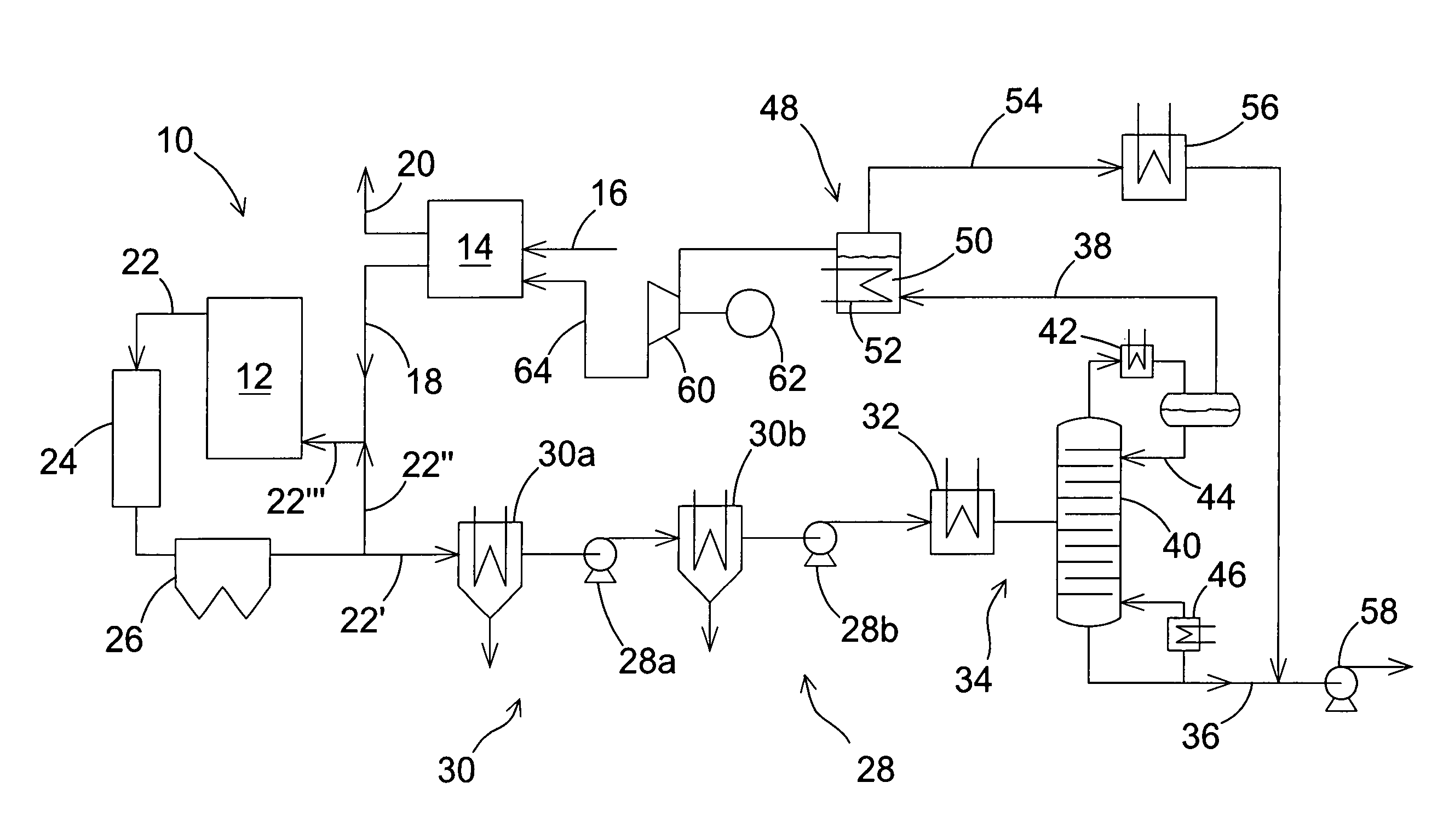
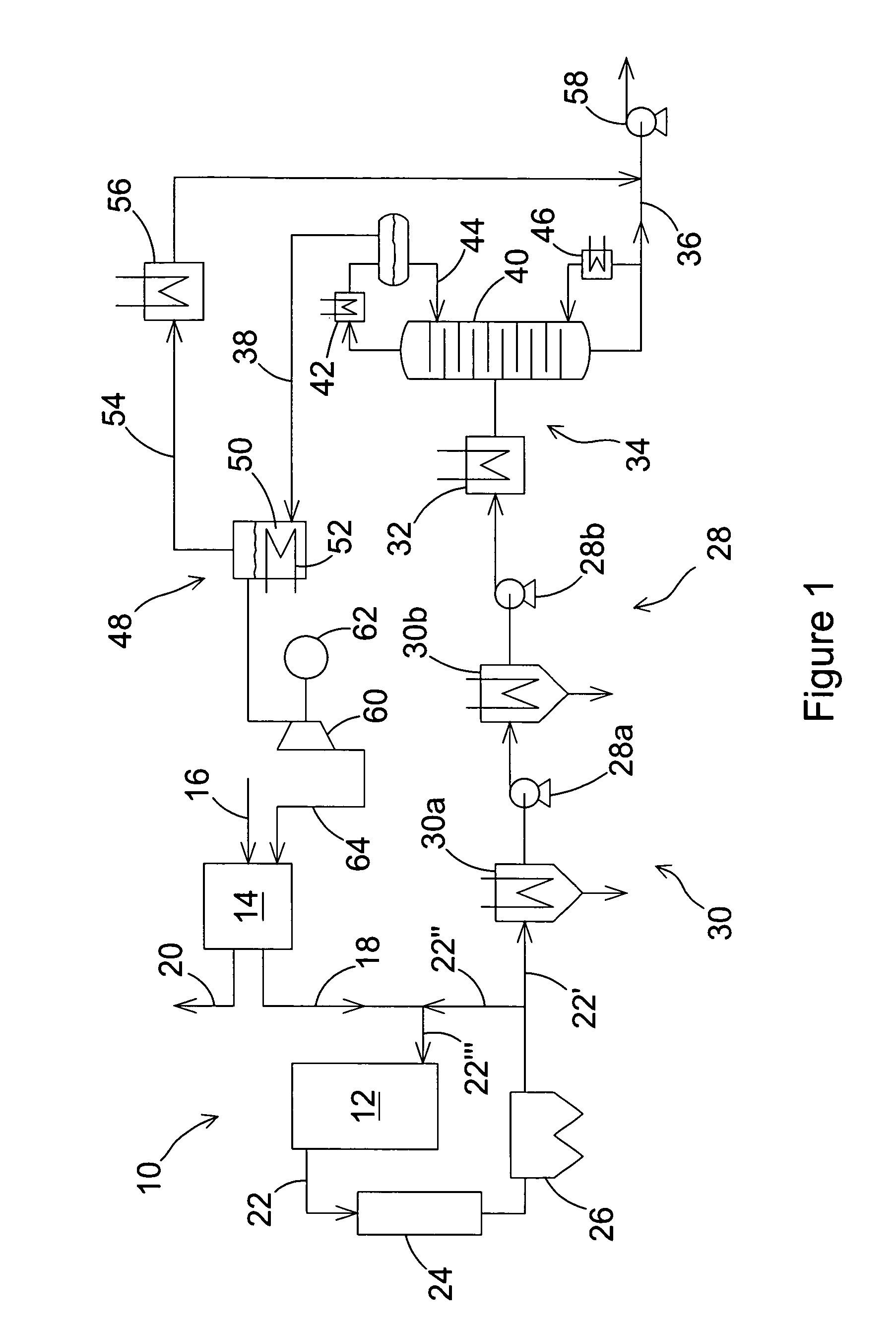
[0028]FIG. 1 discloses schematically a power plant with an exemplary embodiment of the present invention. Thus, FIG. 1 shows a power plant 10, comprising a combustor 12 for combusting carbonaceous fuel with oxygen conducted to the combustor 12 from an air separation unit 14. The combustion process produces a flue gas stream comprising a high amount, for example, about 75%, of CO2 and having water and excess oxygen as its other main components. The combustor 12 may be a CFB boiler, a PC boiler, or some other suitable type of a combustor. The combustor 12 may be operated at about the ambient temperature or it may alternatively be of a type operated at an elevated pressure, for example, about ten bar.

[0029]The air separation unit 14 converts an incoming stream of air 16 to a first stream 18 comprising mainly oxygen, and another stream, nitrogen rich stream 20. According to the present invention, at least a portion of the oxygen rich stream 18 is conducted to the combustor 12, and the n...


PUM

PropertyMeasurementUnit
Temperatureaaaaaaaaaa
Percent by massaaaaaaaaaa

Abstract

A method of and an apparatus for capturing CO2 from flue gas emanating from a carbonaceous fuel combusting power plant, which includes a source of oxygen and a combustion chamber for combusting the fuel with oxygen and thereby producing flue gas that includes CO2, water and excess oxygen as its main components. At least a portion of the flue gas is compressed to a pressure higher than about sixty bar, the compressed flue gas is cooled in a primary CO2 separating unit for capturing a first portion of the CO2 by condensing it to produce a liquid CO2 stream and a high pressure vent gas stream that includes oxygen and excess CO2, the liquid CO2 stream is discharged from the power plant, and the high pressure vent gas stream is conducted to a secondary CO2 separating unit for capturing a second portion of the CO2 by adsorbing it to an adsorbing material.

Description

BACKGROUND OF THE INVENTION[0001]1. Field of the Invention[0002]The present invention relates to a method of and a system for CO2 capture in oxy-combustion. More particularly, the present invention relates to a two-staged CO2 capturing procedure, which optimizes the CO2 cooling duty and compression power.[0003]2. Description of the Related Art[0004]The flue gases of a conventional power station typically contain from about 4% (by volume) to about 14% carbon dioxide (CO2). It is commonly believed that this CO2 represents a significant factor in increasing the greenhouse effect and global warming. Therefore, there is a clear need for efficient methods of capturing CO2 from flue gases so as to produce a concentrated stream of pressurized CO2 that can readily be transported to a safe storage site or to a further application. CO2 has been captured from gas streams by four main technologies: absorption, where CO2 is selectively absorbed into liquid solvents; membranes, where CO2 is separa...

Claims


Application Information

Patent Timeline
IPC IPC(8): B01D53/00B01D53/02C01B32/50
CPCB01D53/002Y02E20/363B01D2253/102B01D2253/108B01D2257/504B01D2259/402F23J15/02F23J15/06F23J2215/50F23J2900/15061F23L2900/07001Y02C10/06Y02C10/08Y02E20/322B01D53/0462Y02E20/30Y02E20/32Y02E20/34Y02C20/40B01D51/06B01D53/02F25J3/08
Inventor FAN, ZHENSELTZER, ANDREW
Owner FOSTER WHEELER ENERGY CORP
Learn More