Micro Lens, Micro Lens Array, and Method of Manufacturing the Same

a micro lens and array technology, applied in the field of micro lens, can solve the problems of weak adhesion to the base material, difficult to form fine lens patterns at a high degree of accuracy, and limited selection of refractive index, so as to reduce the length of the optical path, improve the optical characteristics, and improve the effect of adhesion

Inactive Publication Date: 2008-08-07
PANASONIC CORP
View PDF10 Cites 25 Cited by
  • Summary
  • Abstract
  • Description
  • Claims
  • Application Information

AI Technical Summary

Benefits of technology

[0021]The invention has been developed in view of the problems discussed above, and therefore has an object to provide a micro lens having an excellent resistance to separation, capable of reducing an optical path length, and ensuring satisfactory optical characteristics even when the lens is made finer and provided at higher density, as well as a micro lens array and a manufacturing method of the same.

Problems solved by technology

According to the foregoing methods for providing a layer of resin matrix to the region other than the lens-forming regions, however, the resin is merely attached to the base material with physical absorption, and thus the adhesion to the base material is weak, which readily gives rise to layer separation in the following treatment steps.
It is therefore difficult to form fine lens patterns at a high degree of accuracy when the lens-forming resin is placed on the base material after the resin matrix is formed.
In particular, in the case where the resin matrix is made of resist resin, the kinds of lens-forming resin or solutions to disperse the lens-forming resin are limited due to its easy separation, and the selections of the refractive index are also limited.
The problems discussed above become obstacles when fine micro lenses are formed at a high degree of accuracy.
A reduction of the device in size requires not only to make the lenses per se finer, but also to lessen the lens thickness; however, it is difficult for the methods proposed in the related art to further lessen the thickness.
In addition, because the multi-layer structure is adopted, not only the optical design becomes complex, but also the selections of lens materials are narrowed.
It is therefore necessary to have a large quantity of organic molecules adhere onto the stamp, which makes it difficult to form a monolayer having a uniform thickness.
The monolayer thus formed is not fixed sufficiently because of inactivated organic molecules and therefore readily separates from the base material, which makes the non-affinity unsatisfactory.
In particular, during the formation of the micro lenses in Prior Art 6, since neither the organic molecules are adhered onto the stamp nor they are transferred onto the base material in an atmosphere to prevent inactivation of the organic molecules as described above, it is likely to be insufficient to form a monolayer having excellent non-affinity for the lens material uniformly.
Further, since the method described in Prior Art 7 requires a step of varying the surface energy of the monolayer after the droplets are placed, it is extremely difficult to control the lens shape to be uniform when a lens array is manufactured.
For any of the methods using the monolayer, it is difficult to place a lens material in a specific shape at a specific position on the base material as the lens is becoming finer.
For this reason, problems, such as the occurrence of deformation of the lens shape and a failure to obtain a lens of a specific height become more noticeable.
The influences between the adjacent lenses in close proximity to each other also make it difficult to obtain a uniform lens array.

Method used


Image

  • Micro Lens, Micro Lens Array, and Method of Manufacturing the Same
  • Micro Lens, Micro Lens Array, and Method of Manufacturing the Same
  • Micro Lens, Micro Lens Array, and Method of Manufacturing the Same

Examples


first embodiment

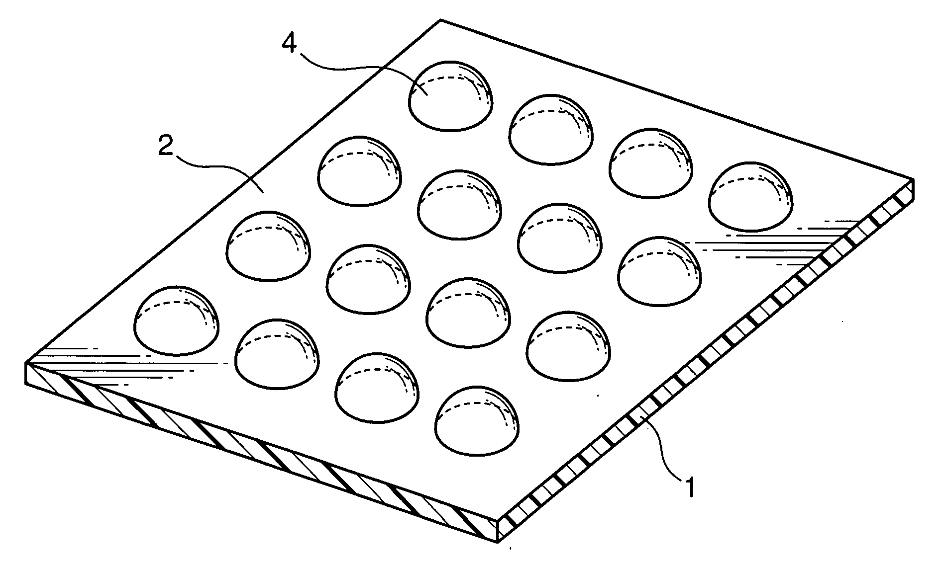
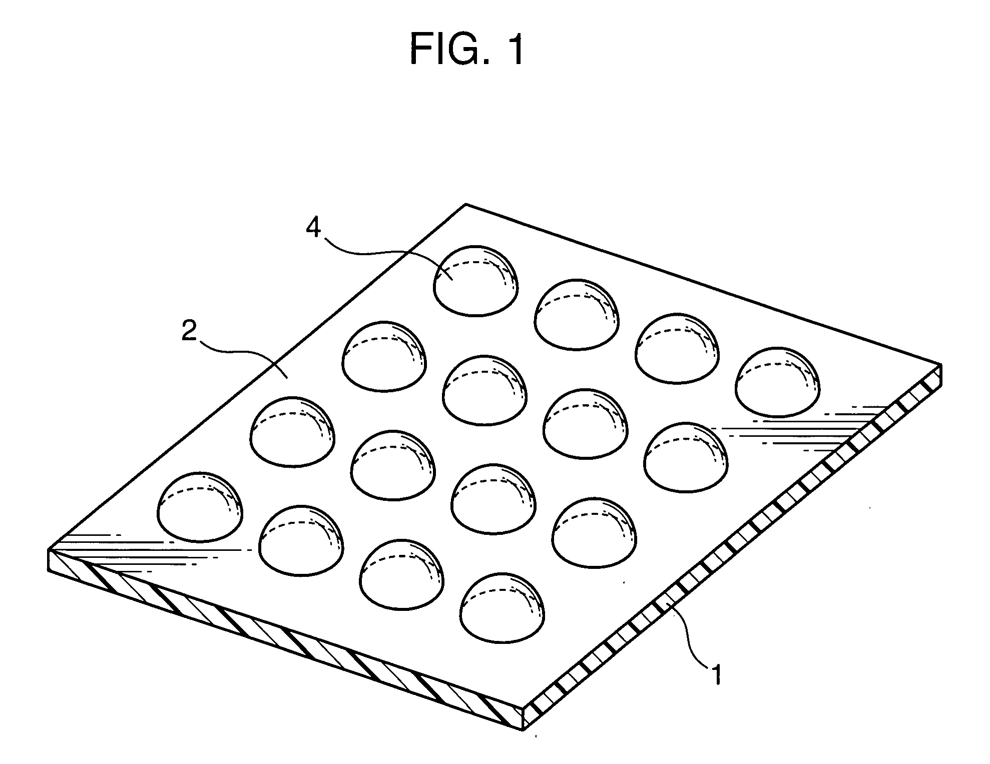
[0040]FIG. 1 will be referred to describe a micro lens of the invention. All drawings showing the micro lens, including FIG. 1, are illustrated schematically for easy understand of the invention, and thus the size, shapes, and so forth do not reflect those adopted actually.

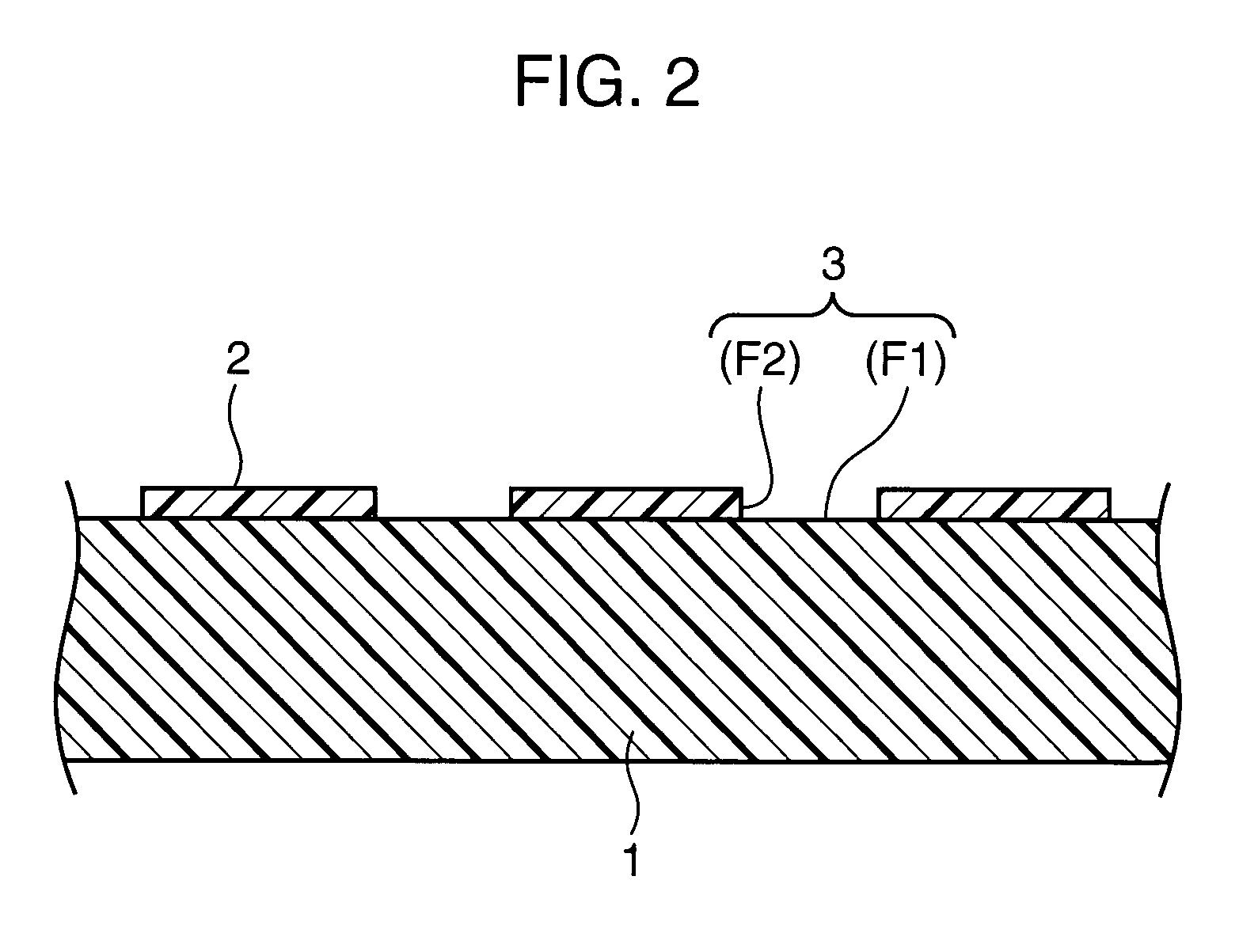
[0041]FIG. 1 is a perspective view showing a micro lens array of the invention. As is shown in FIG. 1, respective lenses 4 are arrayed two-dimensionally on a base material 1. In this embodiment, except for the bottom surfaces of the lenses 4, the entire surface of the base material including the peripheries of the lenses 4 is covered with a first monolayer 2 having non-affinity for a lens material of the lenses 4 in comparison with regions within openings. It may be configured in such a manner as to cover only the periphery of the bottom surface of the opening at which the lens is disposed with the first monolayer 2; however, when the fabrication sequence is concerned, it is advantageous to cover the entire surfac...

second embodiment

[0094]To manufacture the micro lens of the invention, a method different from that in the first embodiment may be adopted for forming the opening. An example of such a method may be a step in which, after the first monolayer is formed, part of the formed first monolayer is removed by irradiation of energy for the opening to be formed selectively on the base material.

[0095]Different from the first embodiment, the resist pattern is not used in this method. Hence, any solvent capable of dissolving the organic molecule can be used without any particular limitation as the aprotic solvent used when preparing the organic-molecule-containing liquid. For example, organic solvents, such as hexadecane, chloroform, carbon tetrachloride, silicone oil, hexane, and toluene, can be used. One kind or a mixture of two or more kinds of these solvents can be used.

[0096]Among them, a mixed solvent containing hexadecane, chloroform, and carbon tetrachloride is preferable as the aprotic solvent. With the ...

third embodiment

[0099]In a manufacture of the micro lens of the invention, when a quantity of active hydrogen on the surface of the base material on which the first monolayer is to be formed is insufficient, it is preferable to provide an active hydrogen providing step before the monolayer forming step. By providing such a step, a selection range of the base materials can be broadened.

[0100]Examples of a method of providing active hydrogen to the base material include a method of subjecting the surface of the base material to a chemical oxidation treatment, a method of applying plasma treatment in the presence of oxygen, a method of performing ozone treatment or the like. Alternatively, there is a method of subjecting the base material to a hydrophilization treatment using, for example, SiCl4, HSiCl3, SiCl3O—(SiCl2—O)u—SiCl3 (where u is an integer from 0 to 6), Si(OH)4, HSi(OH)3, and Si(OH)3O—(Si(OH)2—O)u—Si(OH)3 (where u is an integer from 0 to 6).

[0101]Hereinafter, a method of subjecting the surf...


PUM

PropertyMeasurementUnit
thicknessaaaaaaaaaa
diameteraaaaaaaaaa
diameteraaaaaaaaaa

Abstract

A micro lens includes a base material and a lens formed on the base material, wherein the lens is disposed at an opening on the base material, and the opening is formed by covering a surface of the base material with a first monolayer; and the first monolayer has critical surface energy of 22 mN / m or lower and shows non-affinity for a lens material in comparison with a region within the opening, and is fixed to the surface of the base material via a covalent bind.

Description

TECHNICAL FIELD [0001]The invention relates to a micro lens, a micro lens array, and a method of manufacturing the micro lens.BACKGROUND ART [0002]As a micro lens comprising a lens formed on a base material or a micro lens array comprising plural lenses formed on the base material, of an optical device, that is made of various materials and has various shapes, besides a micro lens made of an inorganic material such as glass, as a lens material, a micro lens made of resin has been proposed in terms of ease of manufacture and a cost advantage. According to the method of manufacturing the micro lens made of resin, because a lens-forming resin solution is placed on the base material and a hemispherical lens shape is formed due to its surface tension, a base material structure such that suppresses diffusion of the resin solution in the region other than the lens forming region is adopted.[0003]For example, Prior Art 1 (Japanese Unexamined Patent Publication No. JP-A-2-262601) proposes a ...

Claims


Application Information

Patent Timeline
Patent Type & Authority Applications(United States)
IPC IPC(8): G02B3/00B05D5/06
CPCG02B3/0012H01L51/5275G02B3/0056H10K50/858
Inventor MINO, NORIHISAYASUHO, TAKEO
Owner PANASONIC CORP
Why Eureka
Try Eureka