
X-ray generation using secondary emission electron source

a secondary emission electron source and x-ray technology, applied in the direction of discharge tube main electrodes, instruments, tomography, etc., can solve the problems of reducing efficiency, limiting the lifespan of such emitters, and limiting the robustness of x-ray tubes, so as to protect from harsh operating environments and operate more efficiently

Inactive Publication Date: 2008-08-07
GENERAL ELECTRIC CO
View PDF3 Cites 34 Cited by
  • Summary
  • Abstract
  • Description
  • Claims
  • Application Information

AI Technical Summary

Benefits of technology

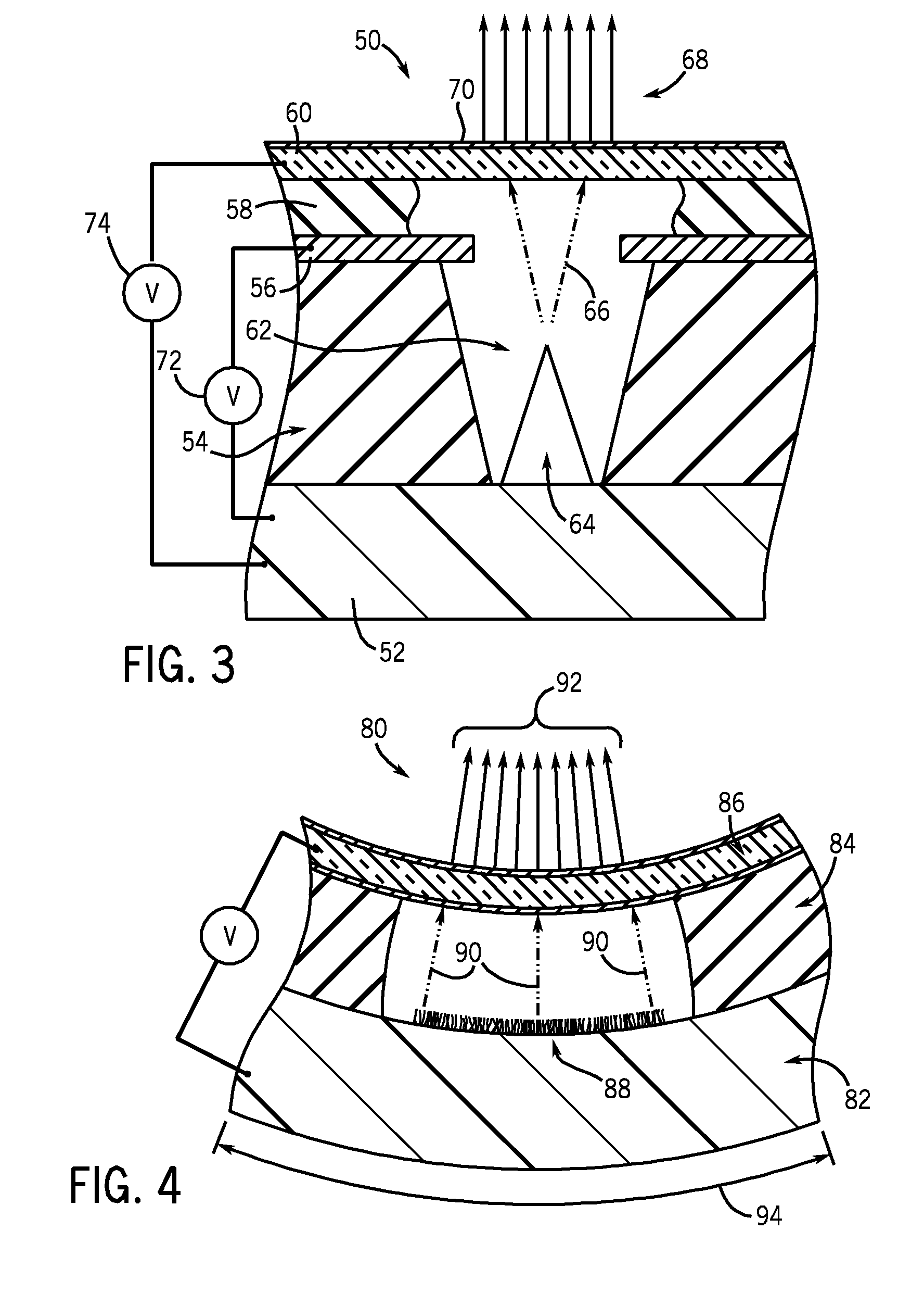
"The present invention is about a method and apparatus for generating x-rays using a secondary emission cathode. This technology allows for more efficient use of the primary electron emitter and protection from harsh operating environments. The invention includes a primary electron source, a controller, a secondary emission component, and an anode. The secondary emission component is positioned in the path of the primary stream of electrons and emits a secondary stream of electrons when it strikes the anode. The controller applies an electrical potential to the primary electron source to cause it to emit a primary stream of electrons, which is then amplified by the secondary emission member. The invention also includes a cathode assembly with a primary electron emitting member, a secondary emission member, and a controller. The secondary emission member amplifies the electron current generated by the primary electron emitting member. The invention also includes an x-ray tube for an imaging system with a housing that encloses an anode and a cathode, where the cathode includes a primary electron emission member and a secondary electron emission member which shields the primary electron emission member. The secondary electron emission member amplifies the electron current generated by the primary electron emitting member. The technical effects of this invention include improved efficiency and protection of the primary electron emitter, as well as improved image quality in x-ray imaging processes."

Problems solved by technology

However, the harsh environment of an x-ray tube can reduce the efficiency over time and limit the lifespan of such emitters.
Thus, these emitters may not be robust enough for use in x-ray tubes due to their chemical, electrical, and physical sensitivity as well as other effects arising from back-bombarding ions, uncontrolled voltages and currents from vacuum arcing, and other particle and radiation exposures.

Method used


Image

  • X-ray generation using secondary emission electron source
  • X-ray generation using secondary emission electron source
  • X-ray generation using secondary emission electron source

Examples


Embodiment Construction

[0026]One operating environment for the present invention is described with respect to a sixty-four-slice “third generationcomputed tomography (CT) system. However, it will be appreciated by those skilled in the art that the present invention is equally applicable for use with other imaging modalities, such as x-ray projection imaging, package inspection systems, as well as other multi-slice CT configurations or systems. Moreover, the present invention will be described with respect to the generation, detection and / or conversion of x-rays. However, one skilled in the art will further appreciate that the present invention is also applicable for the generation, detection, and / or conversion of other high frequency electromagnetic energy.

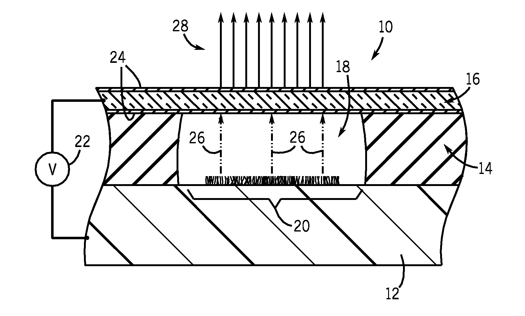
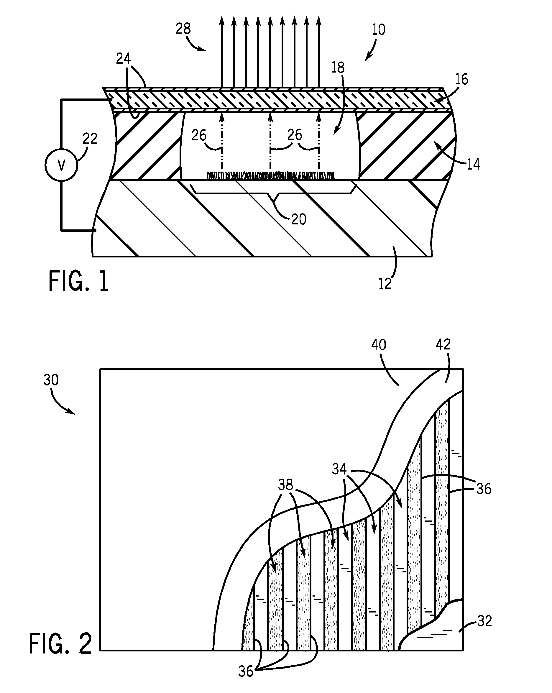
[0027]Referring to FIG. 1, a cross-sectional view of an electron source 10 is depicted. As shown, electron source 10 is a field emitter array; though it is appreciated and will be shown below that other types of electron sources may also incorporate f...


PUM


Abstract

A method and apparatus are provided for generating high frequency electromagnetic energy using a secondary emission electron source. An x-ray source is therefore provided having a primary electron emitter, a secondary emission member, and an anode. The primary electron emitter provides a primary electron current directed to the secondary emission member. The secondary emission member then generates a secondary electron current which causes x-ray generation when impinging upon the anode.

Description

BACKGROUND OF THE INVENTION[0001]The present invention relates generally to the generation of high frequency electromagnetic energy and, more particularly, to a method and apparatus of using a secondary electron emission member in providing an electron stream used to generate x-rays.[0002]X-ray generating systems typically include an electron generating cathode and an anode in a sealed housing. The cathode provides an electron stream or current that is directed toward the anode. Many x-ray tubes include a rotating anode structure for distributing the heat generated at a focal spot. The anode is typically rotated by an induction motor having a cylindrical rotor built into a cantilevered axle. The axle supports a disc-shaped anode target as well as an iron stator structure with copper windings that surrounds an elongated neck of the x-ray tube. The rotor of the rotating anode assembly is driven by the stator. An x-ray tube cathode provides a focused electron beam that is accelerated a...

Claims


Application Information

Patent Timeline
Patent Type & Authority Applications(United States)
IPC IPC(8): H01J35/06A61B6/03
CPCH01J1/32H01J3/021H01J2235/062H01J35/26H01J2235/06H01J35/065
Inventor PRICE, JOHN SCOTTTSAKALAKOS, LOUCASBUI, PIERRE-ANDREDUNHAM, BRUCE MATTHEW
Owner GENERAL ELECTRIC CO
Learn More