Device and method for endovascular treatment for causing closure of a blood vessel

a technology of endovascular treatment and blood vessel closure, which is applied in the field of medical devices and methods for treating varicose vein closure, to achieve the effects of preventing thermal runaway and device damage, reducing power density, and reducing peak temperatures

Active Publication Date: 2008-08-07
ANGIODYNAMICS INC
View PDF102 Cites 49 Cited by
  • Summary
  • Abstract
  • Description
  • Claims
  • Application Information

AI Technical Summary

Benefits of technology

[0017]As can be appreciated, the enlarged light emitting face provides substantially lower power density while providing the same amount of total energy during a treatment session. The reduced power density reduces peak temperatures near the emitting face and prevents thermal runaway and device damage. The reduced average power density from the enlarged emitting face and the spacing of the emitting face away from the vessel wall due to the outer sleeve both serve to reduce the possibility of vessel perforations, leading to less bruising, post-operative pain and other clinical complications.
[0018]In another aspect of the invention, an endovascular treatment method for causing closure of a blood vessel is provided. The method involves inserting into a blood vessel an optical fiber having a core and a spacer sleeve arranged around a distal portion of the core. The distal end of the fiber core defines a light emitting face. Once the optical fiber is inserted, a laser light is applied through the light emitting face while the inserted optical fiber and spacer sleeve are moved longitudinally to treat a defined segment of the b...

Problems solved by technology

Because the ceramic material is brittle, portions of the material can come apart due to heat stress and the outer sleeve surrounding ...

Method used


Image

  • Device and method for endovascular treatment for causing closure of a blood vessel
  • Device and method for endovascular treatment for causing closure of a blood vessel
  • Device and method for endovascular treatment for causing closure of a blood vessel

Examples


Embodiment Construction

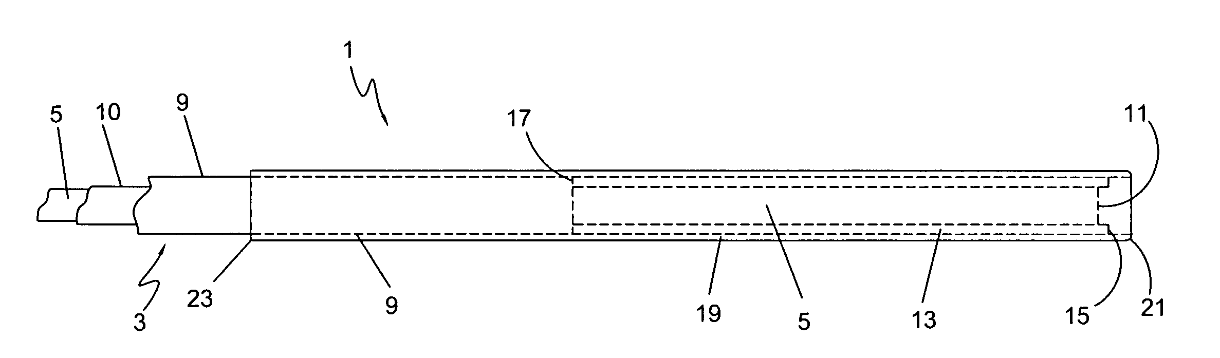
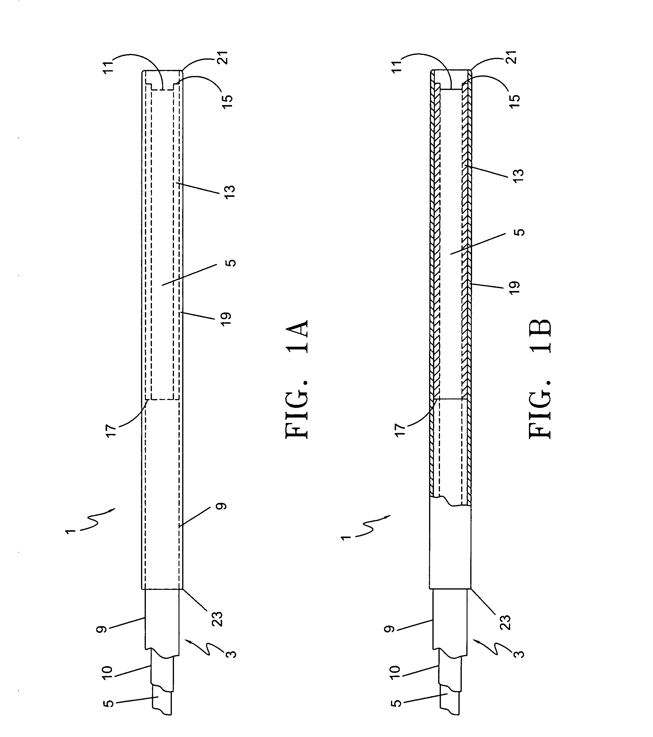
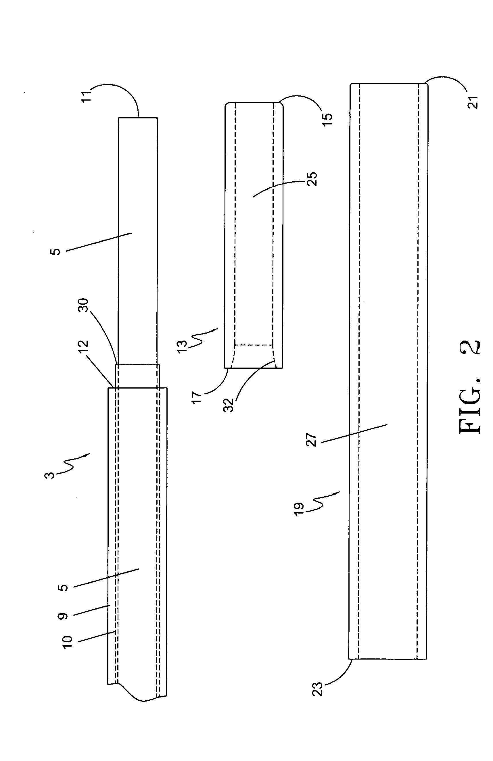
[0043]The following detailed description should be read with reference to the drawings, in which like elements in different drawings are identically numbered. The drawings, which are not necessarily to scale, depict selected preferred embodiments and are not intended to limit the scope of the claims. The detailed description illustrates by way of example, not by way of limitation, the principles of the invention. In various embodiments, and referring to FIGS. 1-14, presented herein are exemplary devices and methods for endovenous laser treatment. FIGS. 1A and 1B illustrate the distal section of one embodiment of the optical fiber with spacer assembly 1 from a partial plan view and partial cross-sectional view, respectively. Optical fiber with spacer assembly 1 is comprised of an optical fiber 3, an insulative inner sleeve 13 and an optional outer protective sleeve 19 coaxially surrounding the inner insulative sleeve 13 and the distal portion of the optical fiber 3. The spacer assemb...


PUM


Abstract

An endovascular laser treatment device for causing closure of a blood vessel uses an optical fiber adapted to be inserted into a blood vessel. An inner sleeve is arranged around a distal portion of the optical fiber core such that both distal ends of the inner sleeve and the optical fiber core form an enlarged light emitting face. The enlarged emitting face provides substantially lower power density while providing the same amount of total energy during a treatment session. An outer sleeve arranged around the inner sleeve acts as a spacer to position the light emitting face away from an inner wall of the blood vessel. The enlarged light emitting face and the outer sleeve acting as a spacer reduces the possibility of thermal run-away and device damage, and reduce the possibility of vessel perforations, leading to less bruising, post-operative pain and other clinical complications. In yet another aspect of the present invention, a spacer comprises an inner sleeve and an outer sleeve both arranged around a distal portion of the core to prevent the laser light from traveling laterally and to position the light emitting face away from an inner wall of the vessel. The inner sleeve can be a heat resistive material such as ceramic and the outer sleeve can be, for example, a metallic sleeve to provide structural integrity and strength to the distal section of the treatment device.

Description

CROSS REFERENCE TO RELATED APPLICATIONS[0001]This application is a continuation-in-part of U.S. application Ser. No. 11 / 777,198, filed Jul. 12, 2007, which is a continuation of U.S. application Ser. No. 10 / 613,395, filed Jul. 3, 2003, now U.S. Pat. No. 7,273,478, which claims priority under 35 U.S.C. Section 119(e) to U.S. Provisional Application Ser. No. 60 / 395,218 filed Jul. 10, 2002, all of which are incorporated herein by reference. This application also claims priority under 35 U.S.C. Section 119(e) to U.S. Provisional Application Ser. No. 60 / 910,743, filed Apr. 9, 2007, U.S. Provisional Application Ser. No. 60 / 913,767, filed Apr. 24, 2007, and U.S. Provisional Application Ser. No. 60 / 969,345, filed Aug. 31, 2007, all of which are incorporated herein by reference.FIELD OF THE INVENTION[0002]The present invention relates to a medical device and method for treating blood vessels, and more particularly to a laser treatment device and method for causing closure of varicose veins.BA...

Claims


Application Information

Patent Timeline
IPC IPC(8): A61B18/20
CPCA61B18/24A61B19/54A61B2017/22068A61B2018/0063A61B2019/446A61B2019/5425A61B2018/00404A61B2018/00101A61B2018/2205A61B90/94A61B90/39A61B2090/3925G02B6/262A61B2017/00526A61B2018/2244G02B6/3855
Inventor APPLING, WILLIAM M.MEYER, RALPH A.BEYER, THEODORE J.HAMILTON, WILLIAM C.BROWN, JOE D.
Owner ANGIODYNAMICS INC
Why Eureka
Try Eureka