
Control Device for a Power Supply with Zero Power Consumption in Standby Mode

a control device and power supply technology, applied in emergency power supply arrangements, power network operation systems integration, instruments, etc., can solve the problems of high standby power consumption, low efficiency of switching power supply units, and common problems of power supply units and functional circuits under light load conditions. achieve the effect of low power consumption

Inactive Publication Date: 2008-08-14
ZHOU XIANPU
View PDF10 Cites 39 Cited by
  • Summary
  • Abstract
  • Description
  • Claims
  • Application Information

AI Technical Summary

Benefits of technology

[0030]The object of the present invention is to provide a control device for a power supply with zero power consumption in standby mode that has extremely low power consumption and can ensure safe standby.

Problems solved by technology

In one aspect, the inefficiency of the power supply unit and the functional circuit of the controlled electrical appliance under light load condition is a common problem in all power devices.
Though the working efficiency of modern switching power supply units under rated load can be as high as 90% or above, the efficiency of those switching power supply units is still very low under light load, resulting in high standby power consumption.
Though the standby power consumption of switching power supply units is reduced increasingly by utilizing low power consuming devices, materials, and leading control structures, such an improving process delivers poor results and the standby power consumption is reduced slowly; in addition, it strongly depends on the manufacturing level of fundamental electronic components and the latest design theories and methods for switching power supply units.
Since the functional circuits of the controlled electrical appliance are usually complex, such renovation will cause increased workload, high technical risk, and longer time cycle of renovation.
The energy saving design for specific electrical appliance is not applicable to other electrical appliances, and requires high financial investment and talent support.
As increasingly strict standby power consumption standards are enacted, electrical household appliance companies will face great renovation pressure.
Apparently, such a scheme requires high direct cost and high renovation cost.
A fatal problem in AC power standby mode is that both the demanding operating environment of electrical household appliances and the weak structure of switching power supply units will result in severe potential safety hazard.
That problem can't be overcome with traditional AC power standby schemes.
3) The power loss of the power supply unit itself can be neglected; the power consumption of the standby power control device in standby mode is the power capacity of the non-AC power supply unit.
That approach can achieve the following three effects:
1) The overall standby power consumption of the complete electrical appliance (measured externally) is equal to zero;
2) It implements intrinsically safe standby since the AC power supply is cut off completely;
3) Since the separate standby power control device is not complex, the power consumption can be very low. Therefore, the microscopic standby power consumption (power capacity of the non-AC power supply unit) of the controlled electrical appliance can be very low.
Viewed from the view point of AC power standby, the power consumption of the separate standby power control device in standby mode is now very low; as a result, the possibility and practicality of further reducing standby power consumption and the corresponding control structure are seldom investigated.
Common problems in those schemes are: high complexity, increased cost, and a variety of problems in the special application environment of electrical household appliances.
However, under the conditions of different light radiation angles and different radiation intensities, the user may feel apparent changes of control sensitivity of the remote controller, and thereby doubt the quality of the product.
1) The battery and the additional circuit may cause apparently increased cost;
2) The controlled electrical appliance must be started up before the end of the discharge cycle of the battery; otherwise the controlled electrical appliance can't be started up due to depletion of battery power. Any other remedial measure will increase operation complexity.
3) The most severe problem is: the service life of a storage battery doesn't match that of the controlled electrical appliance (for example, TV sets usually have a safe service life of 8-10 years).
However, in order to minimize the battery cost, the overall standby current of the standby power control device must be reduced to a tiny level, which is apparently a very tough task.
That scheme tried to utilize the sleep mode of a single-chip microcomputer to reduce the standby power consumption of the control device; in addition, the inventor also recognized the problem of high standby power consumption of existing infrared receiving circuits (working infrared receiving circuit).
However, the drawback in structure is that in sleep mode, the single-chip microcomputer and the peripheral circuit still produce power consumption, two infrared receiving circuits are required and the scheme for processing the power circuit (AC power supply switch) is not provided.
The low power dissipation of the circuit makes no sense if the control of the AC power supply switch can't be settled effectively.
The overall power consumption problem is that the standby power consumption not only comes from the control circuit and infrared receiving circuits, more important, it also comes from abnormal power loss in other parts of the system.
For example, if there is no appropriate control structure, the battery has to supply power to the relay in the long term in case there is no AC power supply unit or the AC power supply unit fails during the process the controlled electrical appliance operates, resulting in severe battery power consumption.
The structure of “front-stage induction circuit” itself is unable to provide very low standby power consumption as expected; therefore, it is difficult to employ a low capacity battery to supply power in the long term.
As a result, any general-purpose remote controller is not suitable; the bandwidth of on-duty circuit is too low, and thereby can only adapt to a few code formats.
In addition, employing a disposable battery to supply power in the long term in Sleep—Wake-UP mode will cause the single-chip microcomputer to be unable to reset in long term due to power shortage.
As a result, once the software system becomes disordered, the entire device can't be recovered to normal operation.
Therefore, the scheme can't solve the problems substantially.

Method used


Image

  • Control Device for a Power Supply with Zero Power Consumption in Standby Mode
  • Control Device for a Power Supply with Zero Power Consumption in Standby Mode
  • Control Device for a Power Supply with Zero Power Consumption in Standby Mode

Examples


Embodiment Construction

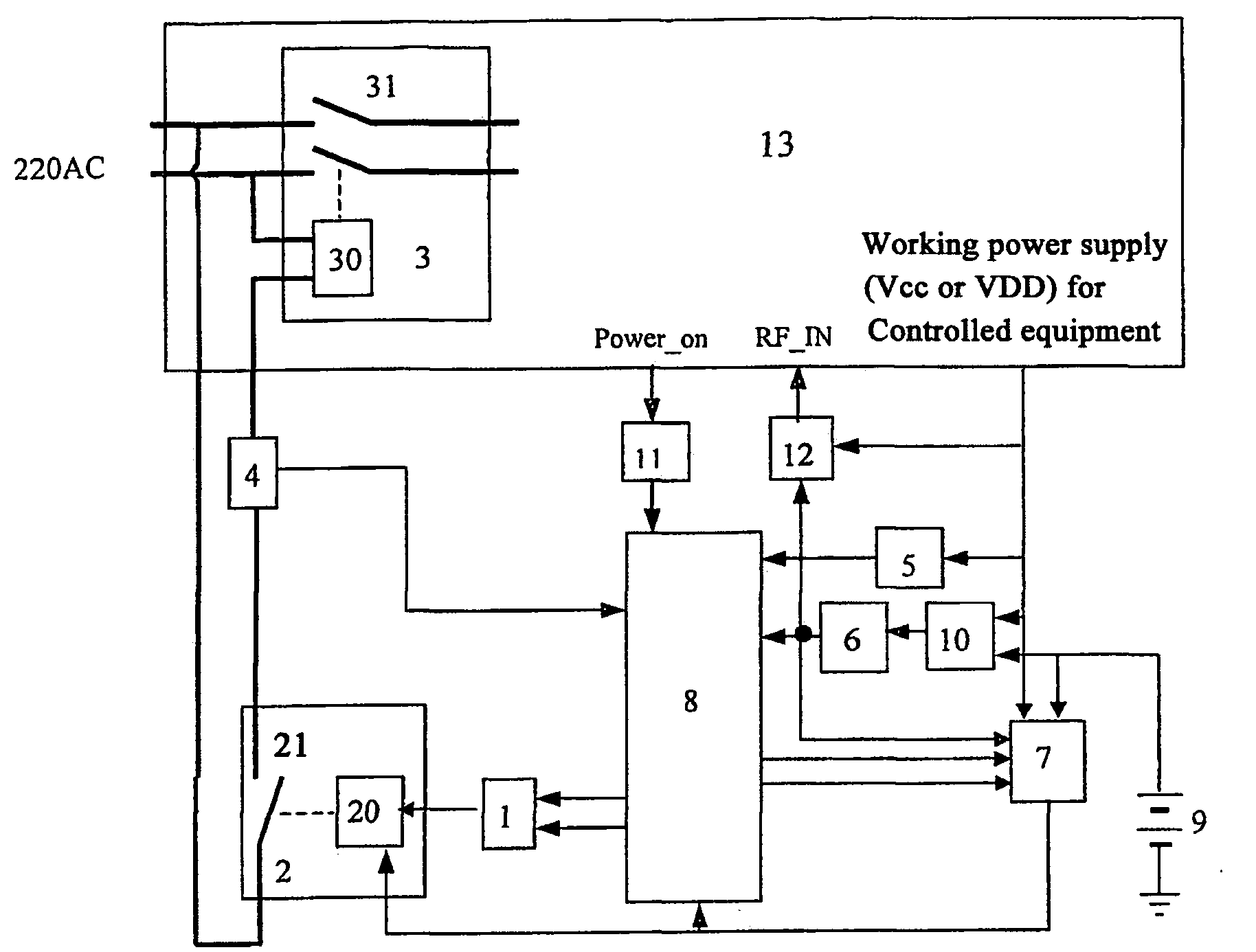
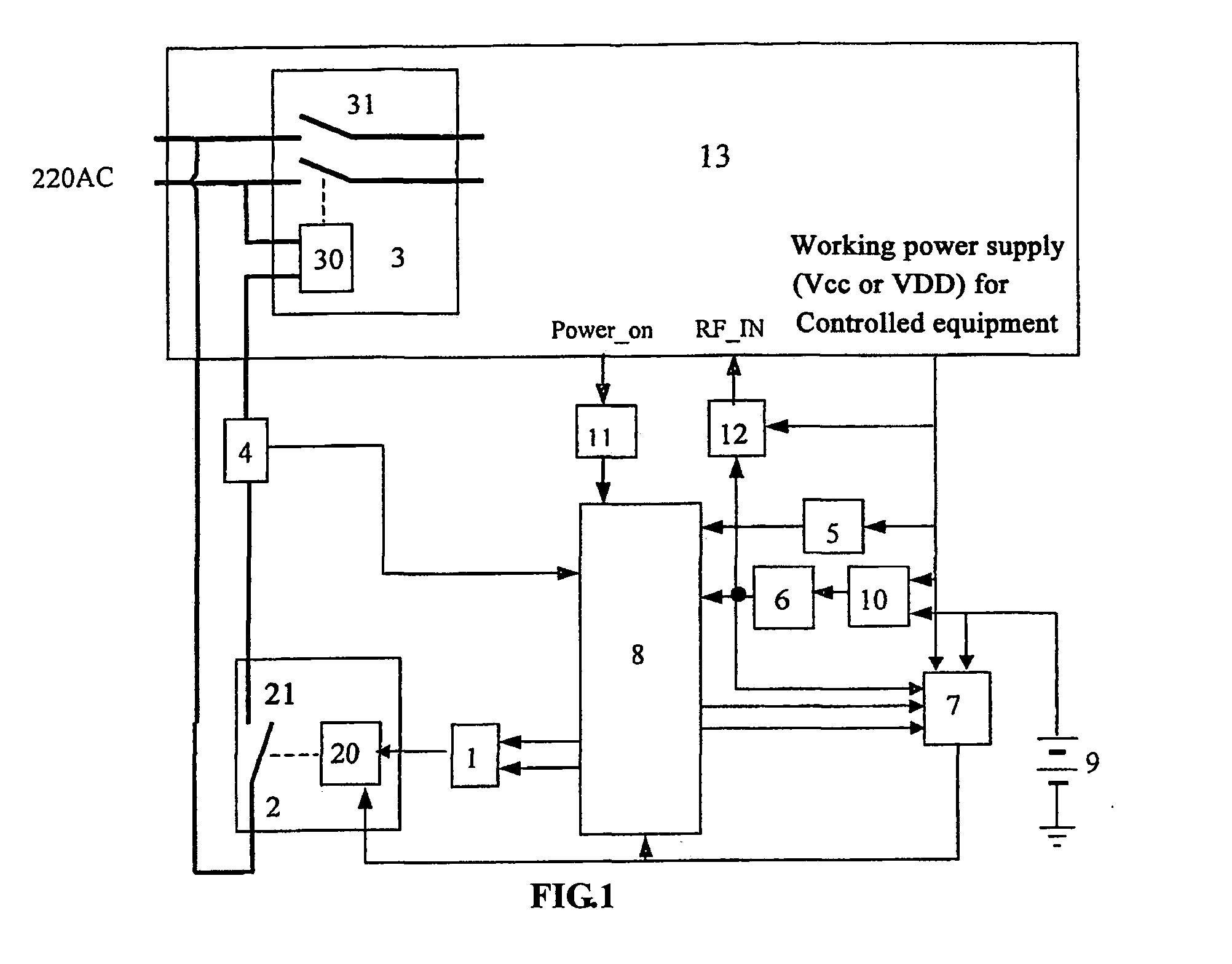
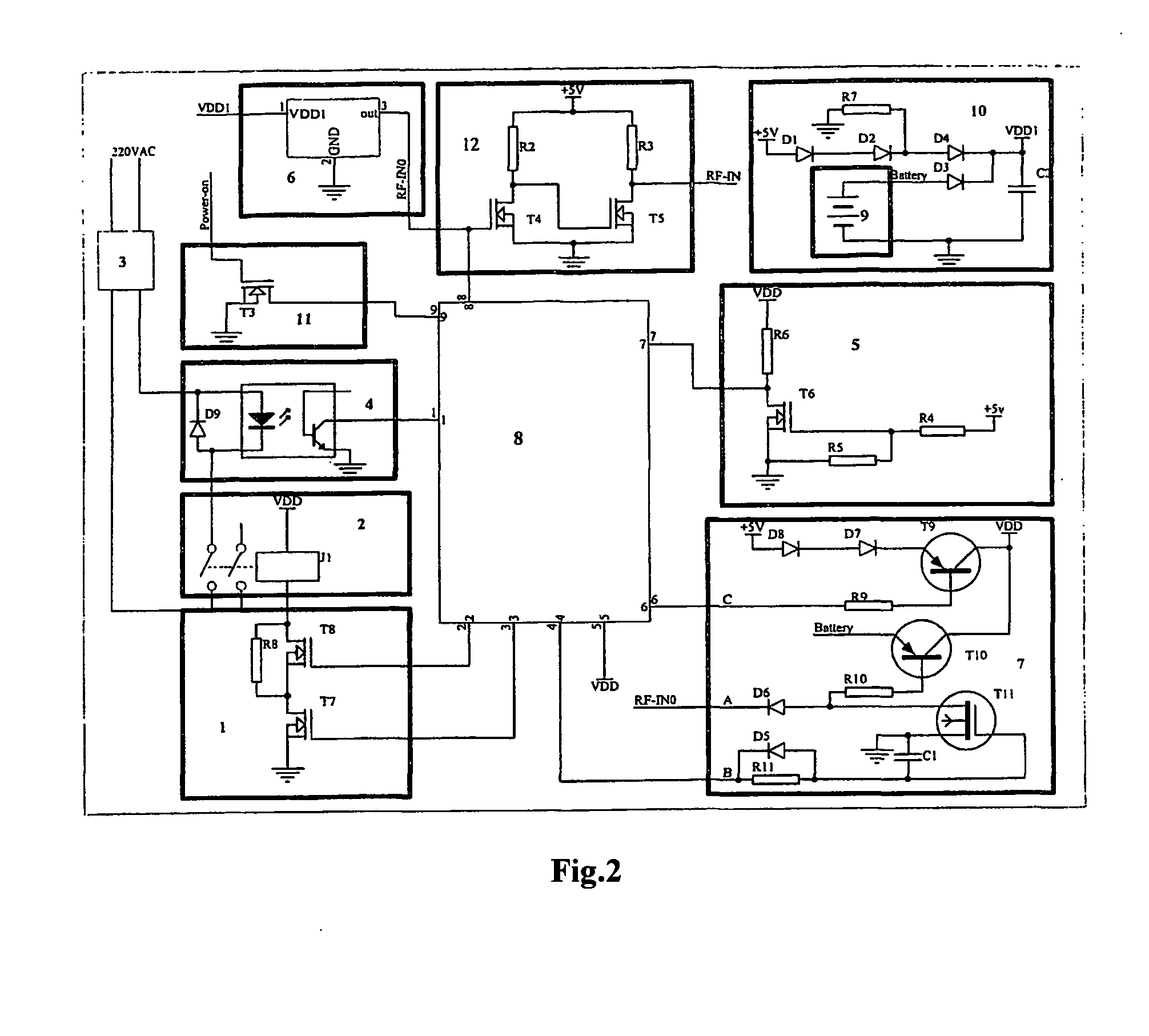
[0068]As shown in FIG. 1, the standby power supply control device with zero power consumption provided in the present invention comprises driver 1, intermediate relay 2, power relay 3, working power supply monitoring circuit 5 for said controlled equipment, signal induction circuit 6, power switching circuit 7, single-chip microcomputer 8, and battery 9; wherein:

[0069]said single-chip microcomputer 8 controls said intermediate relay 2 via said driver 1; the normally-open contact 21 of said intermediate relay 2 are connected in tandem to the coil 30 of said power relay 3 and then cross-connected to two AC power lines; the output of said signal induction circuit 6 is connected to a control end of said power switching circuit 7 and said single-chip microcomputer 8; said battery 9 is grounded at one end and connected to the input end of said signal induction circuit 6 and an input end of said power switching circuit 7; the other input end of said power switching circuit 7 is connected t...


PUM


Abstract

The present invention discloses a kind of control device for a power supply with zero power consumption in standby mode, which includes a driver, an intermediate relay, a power relay, a signal induction circuit, a working power supply monitoring circuit for controlled equipment, a power switching circuit, a single-chip microcomputer and a battery. When a standby command is received by said signal induction circuit, said single-chip microcomputer causes said intermediate relay to cut off the power supply of the controlled equipment and the power switching circuit by said driver. When the controlled equipment is in standby mode, all parts of the control device of the invention are in the off state but the signal induction circuit is powered by the battery, so as to gain safety with low power consumption.

Description

CROSS REFERENCE TO RELATED APPLICATION [0001]This application claims priority to Chinese Application No. 200410062286.2 filed Jul. 5, 2004 and International PCT Application No. PCT / CN2005 / 000963 filed Jul.1, 2005.FIELD OF THE INVENTION [0002]The present invention relates to the electrical household appliance field, particularly to a control device for a power supply with zero power consumption in standby mode applicable to electrical household appliances.BACKGROUND OF THE INVENTION [0003]Presently, the traditional scheme of power control device in electrical household appliance field is:[0004]1) Employ a power supply unit (mainly switching power supply unit) as the standby power supply unit, power off most of the functional circuits, and still use the existing control and signal detection circuits (e.g., single-chip microcomputer and infrared receiving circuit) to control the standby power supply;[0005]2) Employ an assistant AC power supply unit (linear power supply unit or switchin...

Claims


Application Information

Patent Timeline
Patent Type & Authority Applications(United States)
IPC IPC(8): G06F1/26
CPCH02J9/005Y02B70/16H02M2001/0032H02M1/0032Y02B70/10Y02B70/30Y04S20/20H02J9/02
Inventor ZHOU, XIANPU
Owner ZHOU XIANPU
Learn More