Laminated bus bars and methods of manufacture thereof

a technology bus bars, which is applied in the direction of laminated bus bars, cables, insulated conductors, etc., can solve the problems of time-consuming, 45 minutes, energy-intensive process, etc., and achieve the effect of reducing the cost of production and time-consuming

Active Publication Date: 2008-08-21
ROGERS COMMUNICATIONS
View PDF12 Cites 12 Cited by
  • Summary
  • Abstract
  • Description
  • Claims
  • Application Information

AI Technical Summary

Benefits of technology

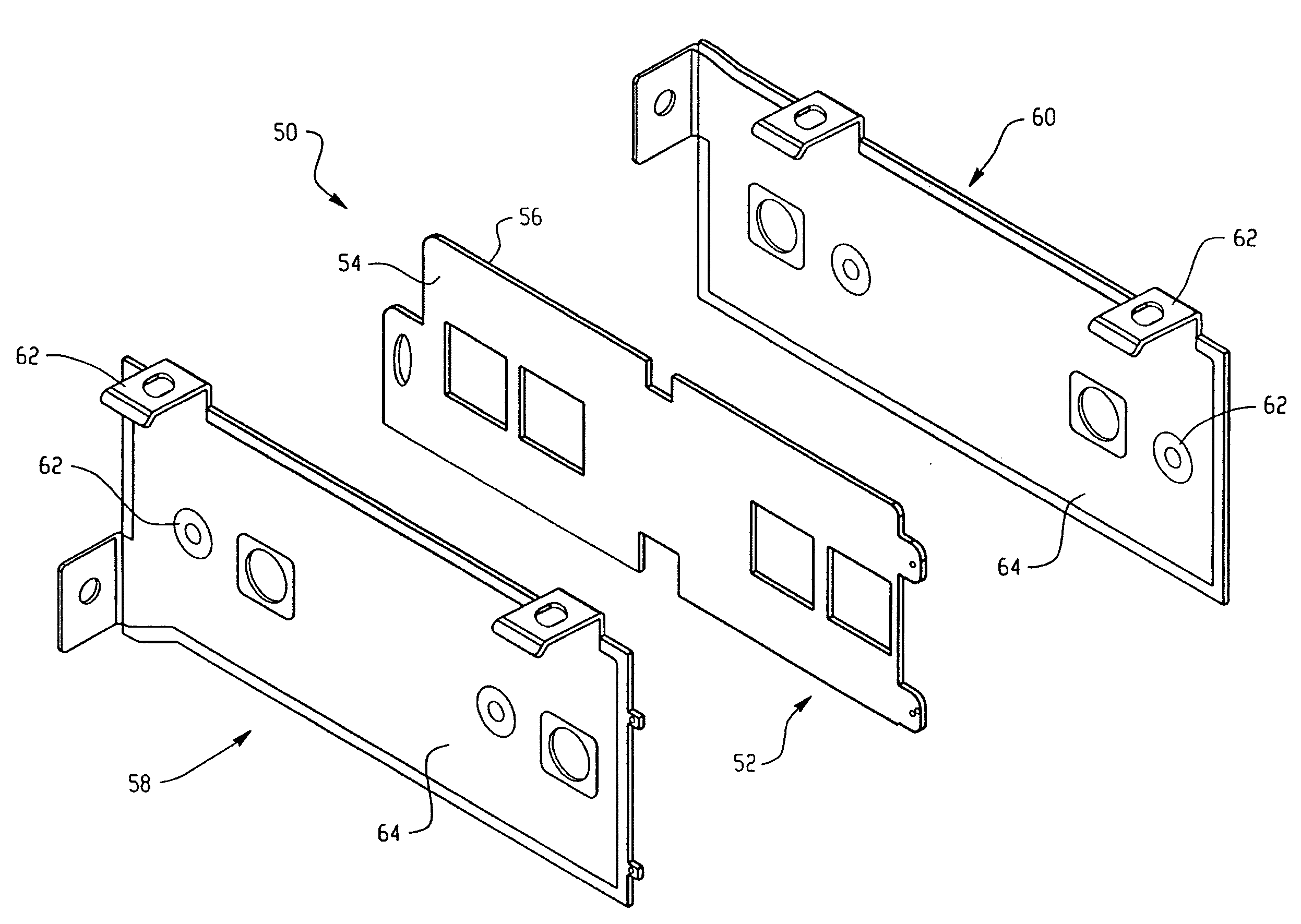
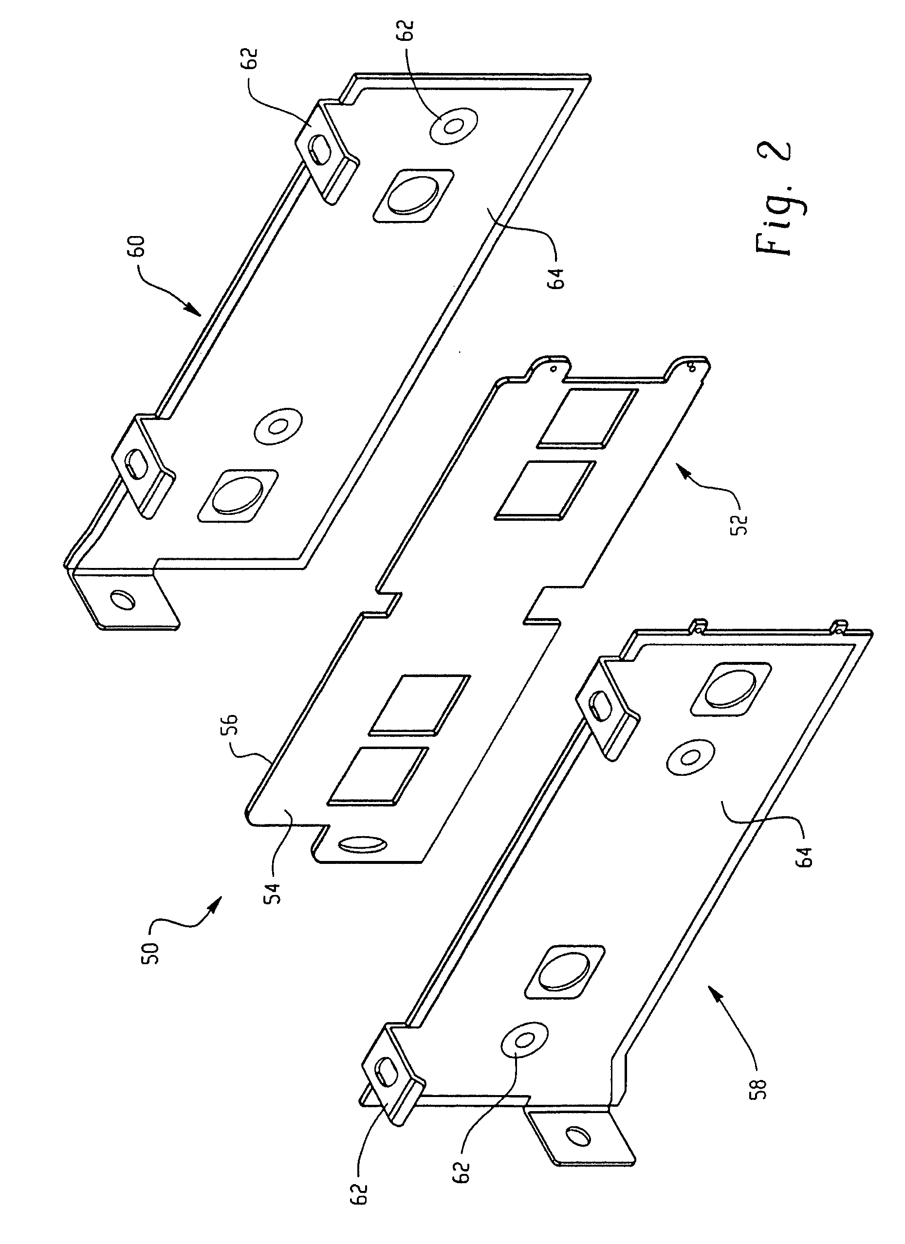
[0010]Disclosed herein is a laminated bus bar assembly, comprising first and second subassemblies, each one of the subassemblies comprising a conductive element, a dielectric layer intermediate the first and second subassemblies, and a reactive hot-melt adhesive adapted to bond the first and second subassemblies to the dielectric layer, wherein the reactive hot-melt adhesive has a cleavage strength between the dielectric layer and a selected one of the first and second subassemblies of at least 1500 Newtons when tested in accordance with ASTM D-1062 with a 25 mm×25 mm sample.
[0011]In another embodiment, a method of assembling a multilayer bus bar assembly includes coating a dielectric layer with a molten reactive hot-melt adhesive, placing a the dielectric layer between first and second subassemblies, wherein the first and second subassemblies comprise a conductive element, adhering the molten reactive hot-melt adhesive to the subassemblies by applying a pressure of at least about one bar to the sandwich for at least about one minute prior to the adhesive cooling to room temperature. Upon complete cure of the adhesive, for example after storage at ambient temperature for 1 to 4 days, the multilayer bus bar assembly has a cleavage strength between the dielectric material and a selected one of the first and second subassemblies of at least 1500 Newtons when tested in accordance with ASTM D-1062 with a 25 mm×25 mm sample.

Problems solved by technology

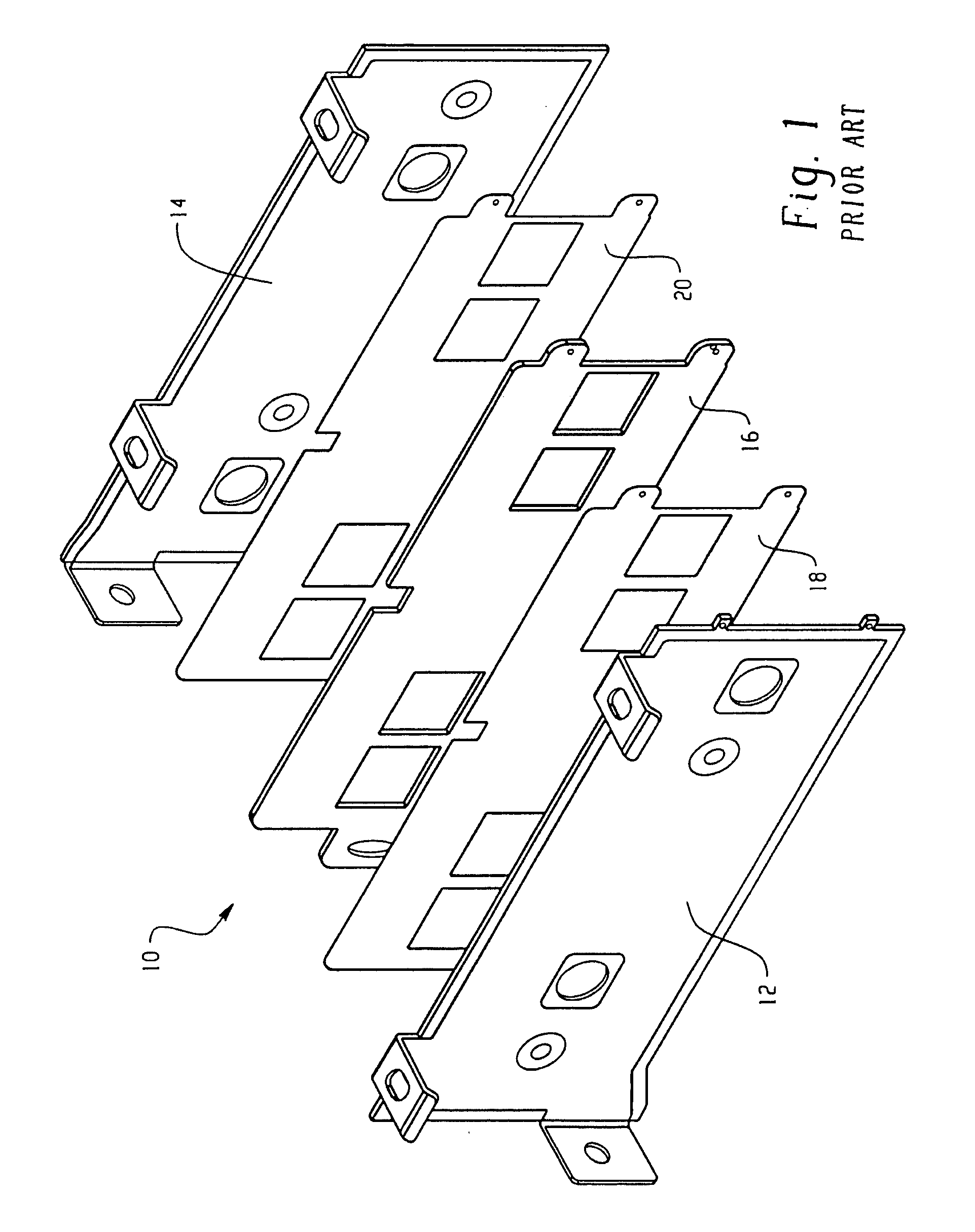
This process can be both time consuming (requiring between 30 and 45 minutes) and energy intensive.
This process is also both time consuming (requiring between 1 and 2 hours) and energy intensive.
A common drawback of this method is that it can be difficult to control the thickness of the adhesive layer.
Another drawback is the method is an untidy process, which requires additional labor.
This method requires additional hardware as well as additional labor.

Method used


Image

  • Laminated bus bars and methods of manufacture thereof
  • Laminated bus bars and methods of manufacture thereof
  • Laminated bus bars and methods of manufacture thereof

Examples


example 1

[0037]An evaluation of the adhesion properties of bus bars made with 3 different types of subassemblies was performed and the results reproduced in Table 1 below. Sample 1 used insulated subassemblies, wherein two bus bar subassemblies, “A” and “B”, were insulated with combinations of white opaque polyester insulation and insulation such as Rogers Induflex® LG4005. To laminate the insulated subassemblies, a layer of 72 grams per square meter (g / m2) of Kleiberit 708.1 polyurethane-based reactive hot-melt adhesive was applied to one side of a pre-tooled 2 mm thick non-woven glass reinforced polyester dielectric layer using a Hardo-GmbH PUR roll coating machine. The coating roll of the machine was set at a temperature of 120° C. and a speed of 5 meters per minute (m / min). The dielectric layer was preheated for 5 minutes to a temperature of 50° C. prior to being coated with the adhesive.

[0038]The adhesive coated side of the dielectric layer was then covered with a precut layer of silico...

example 2

[0045]An evaluation of the electrical properties of a bus bar comprising reactive hot-melt adhesive compared to a second lamination bus bar was performed and the results reproduced in Table 2 below. The partial discharge test measures the extinction voltage and current impulses (Q) of a bus bar insulation material. It is an important measure of potential defects or inhomogeneous insulation material between conductors, as explained in the standard for partial discharge International Electrotechnical Commission (IEC) 60270. The voltage profile, as shown in FIG. 6, is applied between two adjacent layers of the bus bar under test. The initial test voltage is set too high to stimulate the partial discharges. The voltage is then reduced to determine the extinction voltage and to set the partial discharge (PD)-test voltage. The PD level at the PD-test voltage should be below 10 Pico coulombs (pC), as this is the principle partial discharge that will not produce any defect in the insulation...

example 3

[0053]An evaluation of drop test performance of various reactive hot-melt adhesive bonded bus bars compared to second lamination bus bars was performed and the results reproduced in Table 3 below. Drop testing consists of dropping a bus bar from a height of 1.2 m upon a concrete floor. The number of “drops before delamination occurs” is recorded. It is generally required that a bus bar withstand at least 1 drop without delamination in order to be suitable for use in high performance applications. The sample bus bars were drop tested after 5 days storage at ambient conditions; after 3 weeks at 55° C. and 95% RH; and after 100 cycles from −40° C. to 105° C.

[0054]Sample 5 and Comparative sample B used pre-tooled bare copper bars, which were formed into insulated subassemblies by insulating them with Rogers Induflex® LG4005 insulation. One pair of subassemblies was laminated together using Kleiberit 708.1 polyurethane-based reactive hot-melt adhesive by the method described for Sample 1...


PUM

PropertyMeasurementUnit
pressureaaaaaaaaaa
thickaaaaaaaaaa
thicknessaaaaaaaaaa

Abstract

A method of assembling a multilayer bus bar assembly includes coating a dielectric layer with a molten reactive hot-melt adhesive, placing the dielectric layer between first and second subassemblies, wherein the first and second subassemblies comprise a conductive element, adhering the molten reactive hot-melt adhesive to the subassemblies by applying a pressure of at least about one bar to the multilayer bus bar assembly for at least about one minute prior to the adhesive cooling to room temperature to provide a bonding strength between the dielectric material and a selected one of the first and second subassemblies of at least 1500 Newtons on a 25 millimeter by 25 millimeter sample when tested in accordance with ASTM D-1062.

Description

CROSS-REFERENCE TO RELATED APPLICATIONS[0001]This application claims the benefit of U.S. Provisional Application Ser. No. 60 / 890,205 filed Feb. 16, 2007, which is incorporated herein by reference in its entirety.BACKGROUND[0002]This disclosure relates to laminated bus bars, and methods of manufacture thereof.[0003]The electrical power distribution system is an important component in a wide variety of applications such as computer systems, telecommunication equipment, industrial process control, automation cabinets, and the like. Power distribution bus bar systems are also key components of higher voltage applications in electric traction modules and propulsion systems for transportation, such as trains, subways, light rail vehicles, electric / hybrid cars, and the like. For such higher voltage applications, the high power bus bars are devices consisting of relatively thick (0.5 millimeter (mm) to 5 mm) conductive layers and are used to deliver electrical power at low inductance to hig...

Claims


Application Information

Patent Timeline
Patent Type & Authority Applications(United States)
IPC IPC(8): H01B7/08H01R43/00
CPCY10T29/49194H02G5/005
Inventor BEULQUE, MARC
Owner ROGERS COMMUNICATIONS
Why Eureka
Try Eureka