Wire Cleaning Guide

a cleaning guide and wire technology, applied in the direction of manufacturing tools, soldering devices, auxilary welding devices, etc., can solve the problems of deterioration of bonding quality, metal wires such as copper, being susceptible to oxidized, and deteriorating gradually

Inactive Publication Date: 2008-08-21
SHINKAWA CO LTD
View PDF5 Cites 22 Cited by
  • Summary
  • Abstract
  • Description
  • Claims
  • Application Information

AI Technical Summary

Benefits of technology

[0014]It is an object of the present invention to remove foreign substances on the surface of a wire effectively on the path of the wire during bonding.
[0027]The present invention exhibits an advantageous effect that foreign substances on the surface of the wire can be removed effectively on the path of the wire during bonding.

Problems solved by technology

The surface of metal wires such as copper is likely to be oxidized and covered with an oxide film if left in a high-temperature state or in the atmosphere for a long time.
Such an oxide film causes a poor connection during wire bonding and results in a problem of deterioration in bonding quality.
However, in the case of using a coated wire for wire bonding, it is necessary to remove coating on the surface of the wire to expose its metal surface.
Such a surface-active agent is adapted to evaporate near the leading end of a bonding tool of a high temperature, causing a problem in that organic components contained are fixed firmly to the leading end of the bonding tool as contaminations and cause a gradual deterioration in bonding quality such as wire cutting behavior after a long time of use.
It is therefore necessary to replace or clean the bonding tool at a predetermined time interval or after a predetermined number of times of bonding, creating a problem of reduction in bonding efficiency.
Although these conventional arts can remove resin coating on the surface of wires through a high-temperature heat treatment such as induction heating, laser heating, or discharge heating, the high-temperature treatment suffers from a problem in that the surface of the wires is oxidized and covered with an oxide film during the treatment.
However, there is a problem that it is difficult to remove oxide films formed on the surface of wires.
In addition, the high-temperature treatment can cause the mechanical and / or electrical characteristics of wires to be changed, even if the oxide films can be removed, causing a problem in that the changes can cause poor connections and / or poor operation due to a reduction in adhesive performance.
Further, in such a case of using a tensioner as disclosed in Japanese Patent Application Unexamined Publication Disclosure No. 2002-83837, the surface of wires at a high temperature is exposed to air containing oxygen to be further oxidized, creating a further a problem in that the problem of poor wire connections due to surface oxidation gets worse.
Thus, the conventional arts disclosed in Japanese Patent Application Unexamined Publication Disclosure Nos. 5-211196 and 61-214530 and Japanese Patent No. 2723280 suffer from a problem in that foreign substances such as oxide films on the surface of wires cannot be removed effectively.
Although the conventional art disclosed in Japanese Patent Application Unexamined Publication Disclosure No. 61-58246 can prevent thermal oxidation just before bonding of copper wires on which surface oxidation has not yet occurred, oxide films that have already been formed on the surface cannot be removed.
This always requires copper wires with no surface oxidation thereon to be used for bonding, causing a problem of limiting available wires.
Also, if copper wires that have had oxide films formed on the surface thereof are used, the oxide films cannot be removed, creating a problem of deterioration in bonding quality such as a poor connection due to reduction in adhesive performance of the wires.
Also, for the same reason as above, the conventional arts disclosed in Japanese Patent Application Unexamined Publication Disclosure Nos. 61-58246, 5-211196 and 61-214530 and Japanese Patent No. 2723280 suffer from a problem in that surface-active agents applied onto the surface of gold wires cannot be removed effectively and / or easily.
Therefore, even if the method can be applied to wire cleaning, the entire circumference of the wire cannot be cleaned uniformly, suffering from a problem in that a poor connection can occur partially.
Also, in such a method of blowing plasma gas against a wire, the jet changes the path as well as the tension of the wire, causing deterioration in bonding quality such as a poor connection.

Method used


Image

  • Wire Cleaning Guide
  • Wire Cleaning Guide
  • Wire Cleaning Guide

Examples


first embodiment

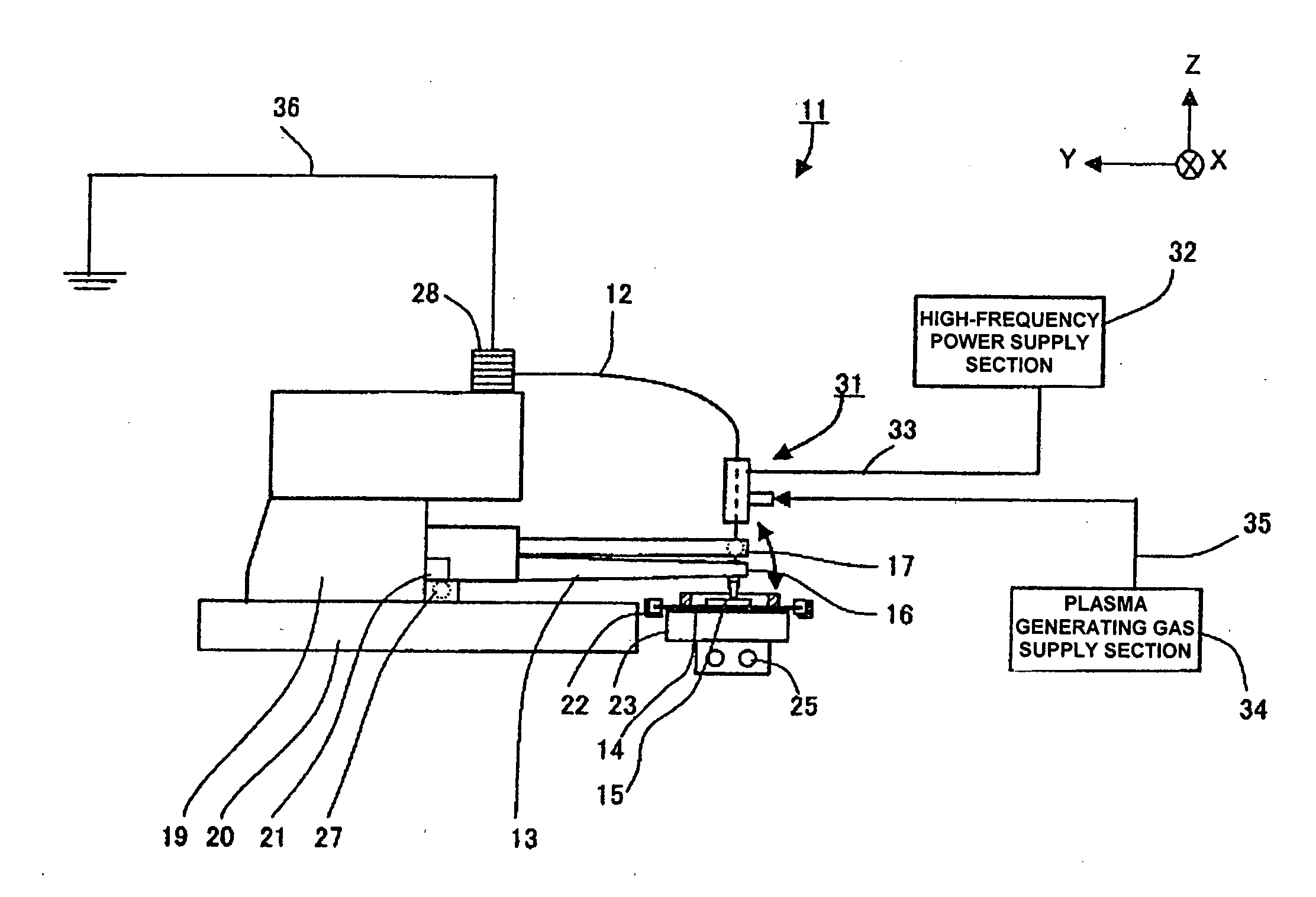
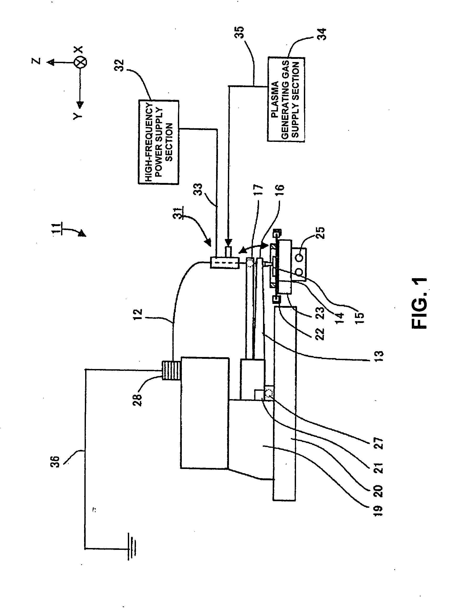
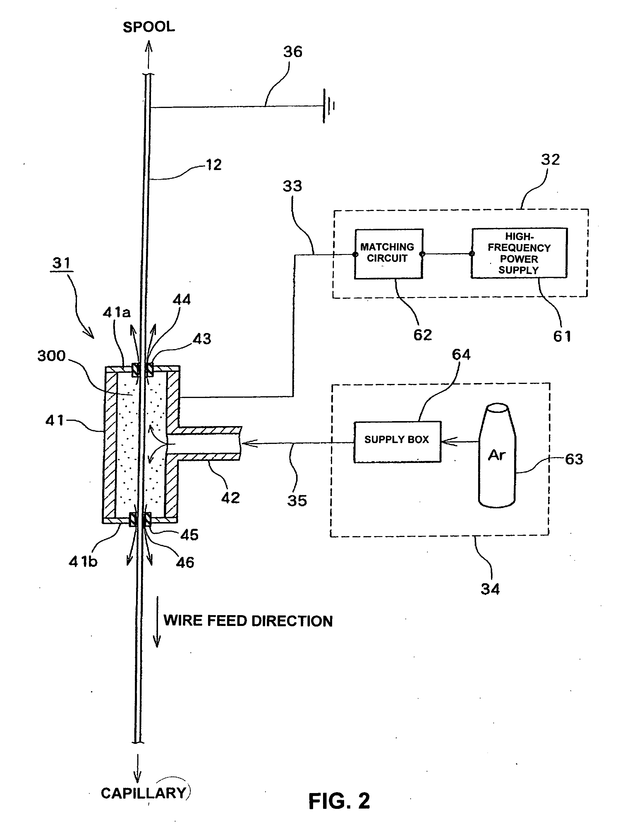
[0044]A wire cleaning guide 31 will be described in detail with reference to FIG. 2. The wire cleaning guide 31 includes a plasma generating chamber 41, a gas supply nozzle 42 for supplying plasma generating gas, and insulation bushings 43 and 45. The plasma generating chamber 41 has a cylindrical shape made of metal such as stainless steel with an inside space for generating plasma and is provided with end plates 41a and 41b, respectively, on the spool and capillary sides. The insulation bushings 43 and 45 are fixed to the center of the respective end plates 41a and 41b. The insulation bushings 43 and 45 are each composed of an insulation member and include guide holes 44 and 46 at the center thereof for guiding the wire 12 there through to guide the wire 12 as well as to provide electrical isolation between the metal wire 12 and the metal plasma generating chamber 41. Also, the insulation bushings 43 and 45 are adapted to keep the metal wire 12 separated from the inner wall of th...

second embodiment

[0052]A second embodiment will be described with reference to FIGS. 4 and 5. As shown in FIG. 4, the wire cleaning guide 31 according to the present embodiment can guide and clean the wire 12 as well as apply a tension toward the spool to the wire 12. Components identical to those in the embodiment described with reference to FIGS. 1 to 3 are designated by the same reference numerals and descriptions thereof are omitted. As shown in FIG. 5, in the present embodiment, the size of the guide hole 44 in the insulation bushing 43 on the spool side is greater than that of the guide hole 46 in the insulation bushing 45 on the capillary side so that the discharge amount of gas after cleaning flowing between the guide hole 44 and the wire 12 is greater than that of gas after cleaning flowing between the guide hole 46 and the wire 12. Therefore, since the force toward the spool that is applied to the wire 12 by the flow of gas after cleaning ejected toward the spool is greater than the force ...

third embodiment

[0054]the present invention will be described with reference to FIG. 6. Components identical to those in the embodiment described with reference to FIGS. 1 to 5 are designated by the same reference numerals and descriptions thereof are omitted. FIG. 6 shows a case where a dielectric 47 such as ceramic or glass is installed inside the plasma generating chamber 41, and the wire 12 is inserted through a guide hole 48 that is opened inside the dielectric 47. Since the dielectric 47 is made of insulating material such as ceramic or glass, the wire 12 can be electrically isolated from the metal plasma generating chamber 41 to be guided. For example, if the diameter of the wire 12 is 20 to 30 μm, the diameter of the guide hole 48 in the dielectric 47 can be 100 to 200 μm. Also, a gas supply hole 49 for communication between the gas supply nozzle 42 and the guide hole 48 is provided in a lateral part of the dielectric 47. The dielectric 47 can be formed in an integrated manner or can be div...


PUM

PropertyMeasurementUnit
frequencyaaaaaaaaaa
diameteraaaaaaaaaa
diameteraaaaaaaaaa

Abstract

A wire cleaning guide for guiding a wire in a feed direction and to clean the wire, including a gas supply nozzle for supplying plasma generating gas, a plasma generating chamber with plasma generating gas supplied from the gas supply nozzle thereto for transforming the plasma generating gas into plasma by energizing a bonding wire that passes there through to clean the wire by means of the plasma gas, and wire-feeder-side and bonding-tool-side guide holes for guiding the wire in the feed direction, the diameter of the wire-feeder-side guide hole is greater than that of the bonding-tool-side guide hole so that the outflow rate of gas after wire cleaning flowing between the wire-feeder-side guide hole and the wire is greater than that of gas after wire cleaning flowing between the bonding-tool-side guide hole and the wire.

Description

BACKGROUND OF THE INVENTION[0001]The present invention relates to a structure of a wire cleaning guide to be used in wire bonding apparatuses and the like.[0002]In semiconductor production processes, wire bonders are often used to provide connections between semiconductor dies and lead frames through metal wires. In such wire bonders, gold wires are used as connection wires. However, with the recent demand for faster and lower-cost semiconductors, metal wires other than gold, such as copper, are often used as connection wires due to its lower-cost but higher-speed signal processing performance.[0003]The surface of metal wires such as copper is likely to be oxidized and covered with an oxide film if left in a high-temperature state or in the atmosphere for a long time. Such an oxide film causes a poor connection during wire bonding and results in a problem of deterioration in bonding quality.[0004]Japanese Patent Application Unexamined Publication Disclosure No. 61-58246 discloses a ...

Claims


Application Information

Patent Timeline
Patent Type & Authority Applications(United States)
IPC IPC(8): B23Q15/00
CPCB08B7/0035B65H57/00H01L2224/45147H01L2224/45139H01L2924/014H01L2924/01006H01L2924/00014H01L2924/30107H01L2924/09701B65H2301/5115H01L24/45H01L24/78H01L24/80H01L24/85H01L2224/45144H01L2224/78301H01L2224/786H01L2224/85009H01L2224/8501H01L2224/85013H01L2224/851H01L2924/01002H01L2924/01004H01L2924/01007H01L2924/0101H01L2924/01018H01L2924/01029H01L2924/01033H01L2924/01047H01L2924/01075H01L2924/01079H01L2924/01082H01L2224/48H01L2924/00H01L2224/45015H01L2224/7801H01L2224/85205H01L2924/00011H01L2924/181H01L2924/00015H01L2924/01049H01L2924/20752
Inventor HORINO, MASAYUKIFUJITA, KAZUO
Owner SHINKAWA CO LTD
Why Eureka
Try Eureka