Image Projector

a projector and projector technology, applied in the field of image projectors, can solve the problems of affecting the optical system of the projector, affecting the performance of the projector, and the life of the above-mentioned lamp or the like, and achieve the effect of reducing the generation of speckle nois

Inactive Publication Date: 2008-08-21
PANASONIC CORP
View PDF8 Cites 66 Cited by
  • Summary
  • Abstract
  • Description
  • Claims
  • Application Information

AI Technical Summary

Benefits of technology

[0020]According to the extremely simplified configuration of the optical system of the image projector of the present invention wherein the reflector element being mounted in the optical system vibrates, reduction of speckle noise generation is achieved.

Problems solved by technology

It is unfortunate, however, that the above said lamp or the like has relatively short lifetime.
Hence, when the above said lamp or the like is used as a light source, it is a hassle to maintain the light source.
So it complicates an optical system of the projector.
Accordingly, the color reproduction region of the projector is confined within a restricted narrow area and, hence, it is difficult to deliver a vivid pure color.
Moreover, the image projector of this type has an issue of low light use efficiency.
When the laser light source is used in the image projector as described above, however, there is a problem that inherent coherency (nature of being prone to interfere) of laser light causes speckle noise to be found in an image and, as a consequence, it deteriorates the picture quality of the projected image.
For practical use of the image projector that uses a laser as a light source, there still remains the serious problem of reducing the generation of the speckle noise.

Method used


Image

  • Image Projector
  • Image Projector
  • Image Projector

Examples


embodiment 1

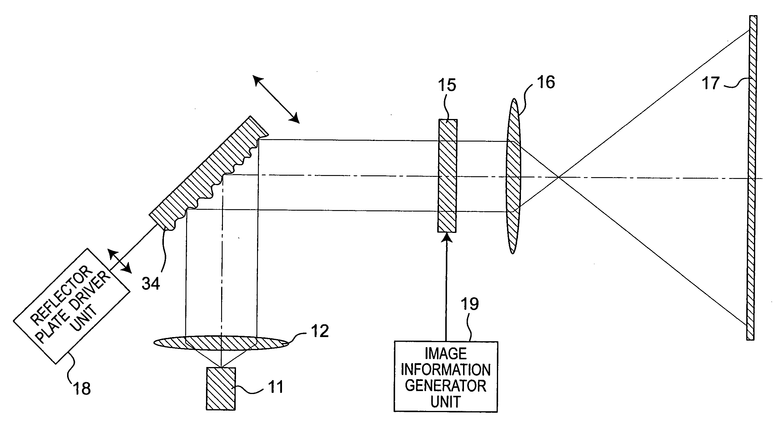
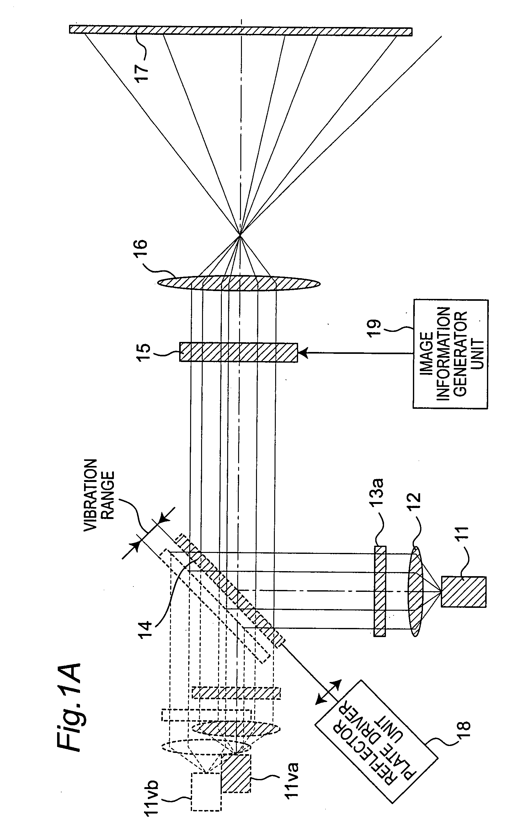
[0040]FIG. 1A is a schematic diagram of an image projector according to first embodiment.

[0041]The image projector of the present embodiment includes a semiconductor laser 11 as a laser light source (a coherent light source). The image projector includes in order along a optical path of laser light output from the semiconductor laser 11: a collimator lens 12 which transforms divergent light to collimated light; a diffuser element 13; a reflector plate 14 as a reflector element; a transmissive liquid crystal spatial modulator element 15 as a spatial modulator element; a projector lens 16 of a projector optical system; and, a screen 17. In addition, the image projector includes a reflector plate driver unit 18 as reflector element driver means and an image information generator unit 19 as image information generator means. The dashed-dotted line represents a optical axis of the laser light output from the semiconductor laser 11. The elements depicted by dashed lines illustrate: one di...

first embodiment

Modification of First Embodiment

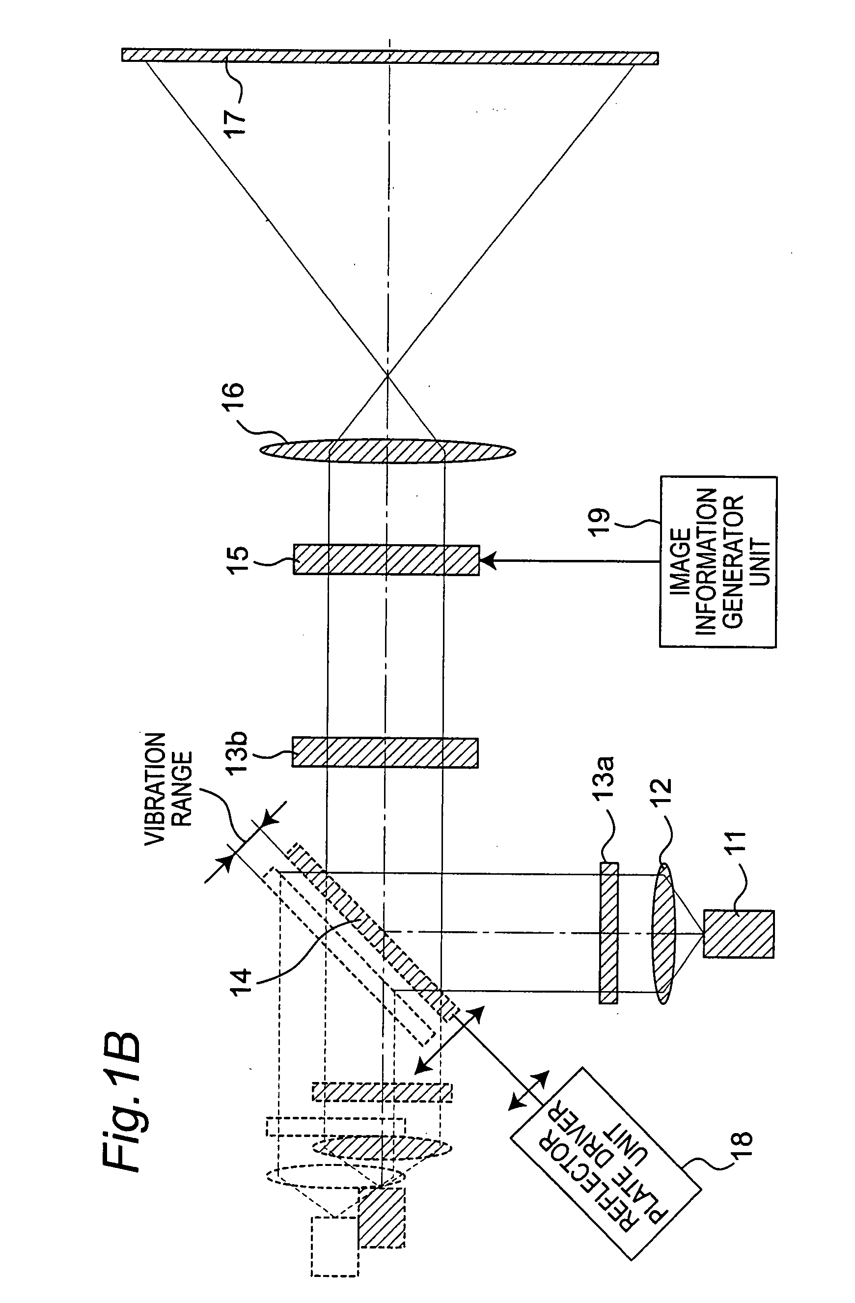
[0054]FIG. 1B is a schematic diagram of an image projector according to a modification of the first embodiment.

[0055]Similarly to the image projector of the first embodiment shown in FIG. 1A, the image projector of the present modification includes: a semiconductor laser 11; a collimator lens 12; a first diffuser element 13a; a reflector plate 14; a transmissive liquid crystal spatial modulator element 15; a projector lens 16; a screen 17; a reflector plate driver unit 18; and, an image information generator unit 19. In addition, this image projector includes a second diffuser element 13b on the optical path between the reflector plate 14 and the transmissive liquid crystal spatial modulator element 15.

[0056]Laser light from the semiconductor laser 11 enters the collimator lens 12 and is transmitted through the first diffuser element 13a, and then changes its direction of travel by almost right angle at the reflector plate 14 which is arranged such th...

second embodiment

[0060]FIG. 2 is a schematic diagram of an image projector according to second embodiment.

[0061]Similarly to the image projector of the first embodiment, the image projector according the present embodiment includes: a semiconductor laser 11; a collimator lens 12; a transmissive liquid crystal spatial modulator element 15; a projector lens 16; a screen 17; a reflector plate driver unit 18; and, an image information generator unit 19. In addition, this image projector includes a diffuser element 23 and a reflector plate 24 on the optical path between the collimator lens 12 and the transmissive liquid crystal spatial modulator element 15, both of which are structurally-integrated in a single-piece and functions as a diffuser element as well as a reflector element, and the diffuser element 23 is formed in front of a reflector surface of the reflector plate 24.

[0062]The reflector plate 24 and the diffuser element 23 which is integrally formed in front of the reflector surface of the refl...


PUM


Abstract

An image projector realizing image projection with high image quality by reducing speckle noise. An image projector comprising a coherent light source, a collimation lens for transforming coherent light emitted from the coherent light source into coherent parallel light, and a projection optical system for projecting coherent parallel light is further provided with a reflection element for reflecting the coherent parallel light and capable of oscillating in parallel with the direction normal to the reflection plane, and a reflection element drive means for causing oscillatory motion of the reflection element.

Description

TECHNICAL FIELD[0001]The present invention relates to an image projector or a visual display such as a television receiver, an image projector, and a semiconductor exposure apparatus, and more particularly, to an image projector using a coherent light source as a light source.BACKGROUND ART[0002]In recent years, an image projector using a metal halide lamp, halogen lamp, Xenon arc lamp, high-pressure mercury discharge lamp, or the like (referred to as “a lamp or the like,” hereinafter,) as a light source have become common. For the image projector of this type, output light from the lamp or the like being used as a light source is separated into red light (long-wavelength light), green light (intermediate-wavelength light), and blue light (short-wavelength light) by means of a wavelength selective mirror. Each separated light of such colors is modulated separately by a liquid crystal panel. Then, the separated and modulated light is multiplexed by a dichroic prism and projected onto...

Claims


Application Information

Patent Timeline
Patent Type & Authority Applications(United States)
IPC IPC(8): G03B21/28
CPCG02B27/48G03B21/28G03B21/10
Inventor KASAZUMI, KEN'ICHIHORI, YOSHIKAZU
Owner PANASONIC CORP
Why Eureka
Try Eureka