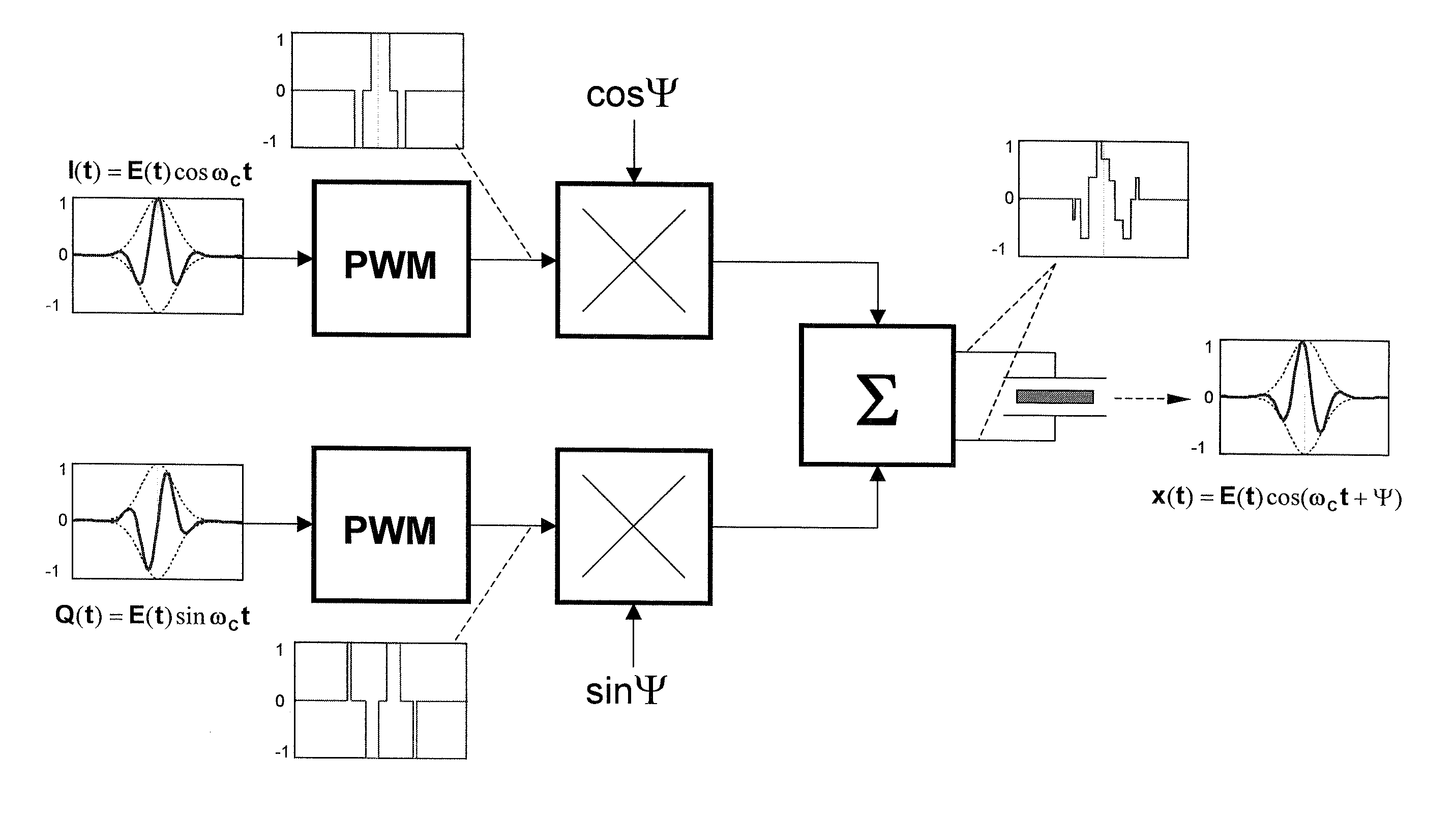
Ultrasound transmit beamformer integrated circuit and method
a beamformer and ultrasonic technology, applied in the field of coherent ultrasound imaging systems, can solve the problems of insufficient hardware resources to optimize the characteristics of transmit waveforms, insufficient programmability of carrier frequency characteristics, and insufficient precision of transmit waveforms, so as to achieve the effect of reducing cost, ensuring programmability, and reducing power consumption
- Summary
- Abstract
- Description
- Claims
- Application Information
AI Technical Summary
Benefits of technology
Problems solved by technology
Method used
Image
Examples
first embodiment
[0041]In a first embodiment shown in FIG. 6, there are two identical pulse height and width multipliers, 601 and 602, driving a transformer 613. In operation, said multipliers 601 and 602 receive the primary I / Q PWM-sequences labeled SEQ_IP / N and SEQ_QP / N, respectively. Each of said PHWMs comprises two identical branches operating as an on / off switchable current driver. The switchable current driver includes a resistor 603, an open-drain switch 604, a 2:1 multiplexer 605 and a transistor amplifier 606 connected in a common gate configuration. The gate of the amplifier 606 is fed by a DAC 612. In alternative embodiment, a bipolar transistor in a common base configuration may be used. In other alternative embodiments, different current drivers, such as conventional current mirrors, may be provided. In another alternative embodiment, an open collector switch may be employed. Regardless on the implementation, the current flowing trough the resistor 603 is proportional to the DAC output ...
second embodiment
[0044]Since the gate voltage in FIG. 6 is formed as a product of phase rotating and apodization factors, it may have a wide dynamic range. Consequently, the threshold voltage tolerance of the transistor amplifiers may degrade the accuracy of beamformation. In view of that, the second embodiment shown in FIG. 5 introduces a different architecture.
[0045]FIG. 5 depicts the second embodiment 500 comprises two identical pulse height and width multipliers 501, 520, a transmit controller 570, and an output multiplier 580. Each of the PHWMs 501 and 520 comprises two identical programmable current drivers 530, 540 and 550, 560. Interface and architecture of these drivers are shown in FIG. 7.
[0046]Referring to the PHWM 501, the first and second clock terminals 504, 506 of the first and the second drivers are connected in reverse. These terminals are fed by the PWM pulse train as discussed previously.
[0047]Switching inputs 508 of the first and second drivers 530, 540 are controlled by the pola...
PUM
 Abstract
Description
Claims
Application Information
 - R&D
- Intellectual Property
- Life Sciences
- Materials
- Tech Scout
- Unparalleled Data Quality
- Higher Quality Content
- 60% Fewer Hallucinations
Browse by: Latest US Patents, China's latest patents, Technical Efficacy Thesaurus, Application Domain, Technology Topic, Popular Technical Reports.
© 2025 PatSnap. All rights reserved.Legal|Privacy policy|Modern Slavery Act Transparency Statement|Sitemap|About US| Contact US: help@patsnap.com


