
Selecting Delay Values For a Rake Receiver

a delay value and receiver technology, applied in the field of selecting delay values for rake receivers, can solve the problems of fading, significant decrease of the magnitude, or fading, of the path gain for the path, and interference in the receiver, so as to improve the effect of saving computational resources and improving the ability of selecting correct and accurate path delays

Inactive Publication Date: 2008-08-28
TELEFON AB LM ERICSSON (PUBL)
View PDF2 Cites 6 Cited by
  • Summary
  • Abstract
  • Description
  • Claims
  • Application Information

AI Technical Summary

Benefits of technology

[0015]By monitoring the signal-to-interference ratio values around the delays from the path searcher and then relocating the fingers of the RAKE according to the highest signal-to-interference ratio values, the performance of the receiver is improved considerably in time-critical cases such as paging, because quite accurate delay values can be provided in a very short time after wake-up of the receiver. At the same time, since the signal-to-interference ratio values need only be calculated for a few delay values around each peak, the required computational resources can still be kept at a low level.
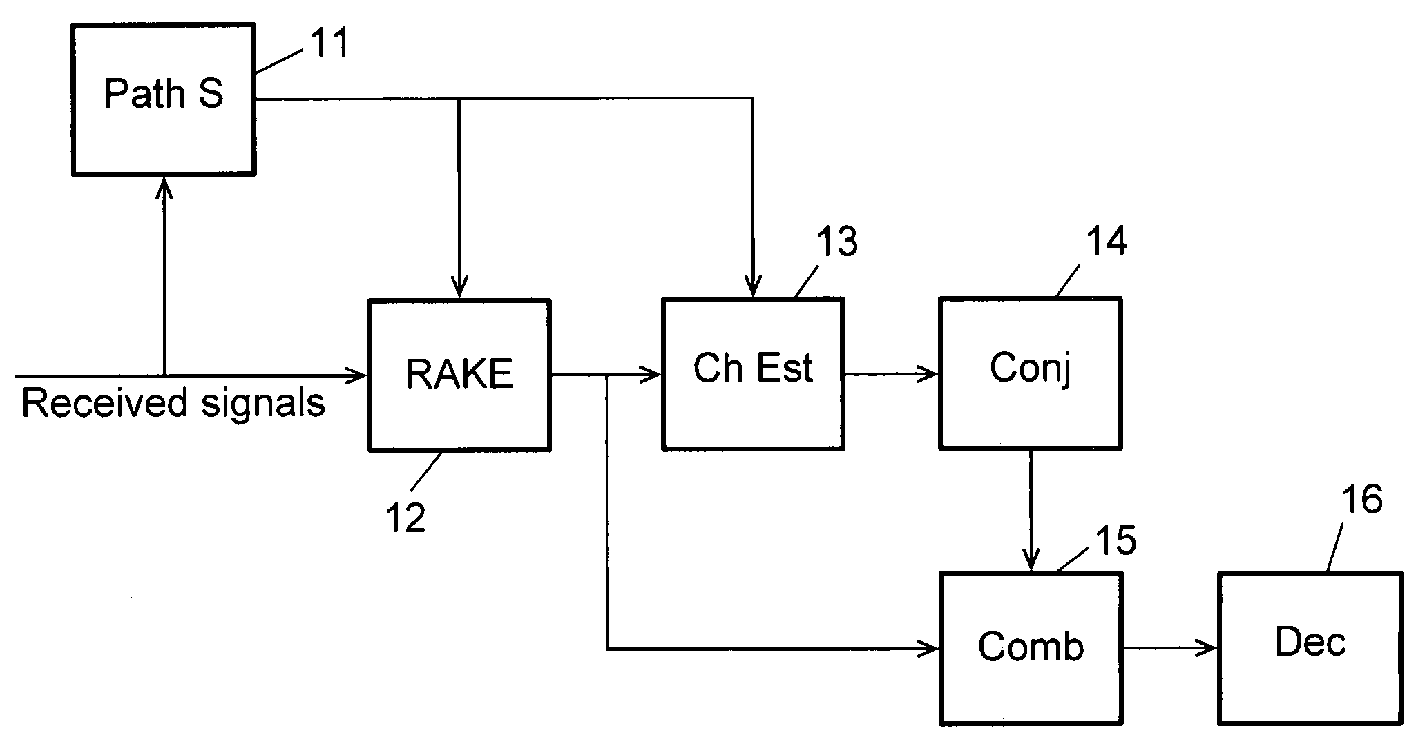
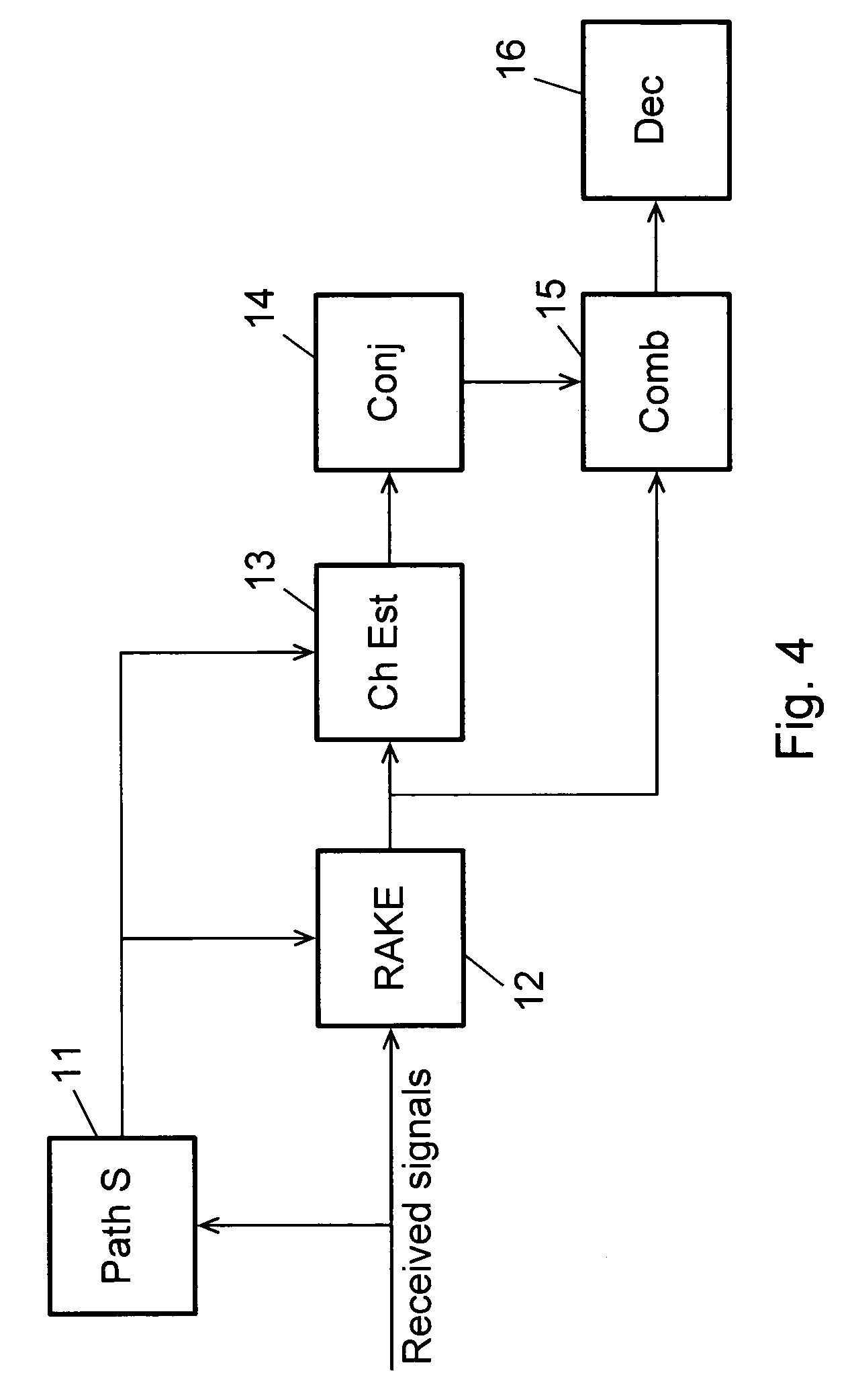
[0018]In another embodiment, the method further comprises the steps of storing received signals; processing received signals to obtain pilot symbols; using said pilot symbols in the calculation of said signal-to-interference ratios; processing stored signals to obtain user data symbols corresponding to said selected delay values; calculating channel estimates for each of said selected delay values; and combining said channel estimates with said provided user data symbols. By storing the received signals and then after the delay values for the RAKE fingers have been selected processing the user data signals only for the selected delays, computational resources can be saved.
[0019]As mentioned, the invention further relates to a receiver for digital data symbols sent from a transmitter through a transmission channel of a communications network, in which individual multipath components of a transmitted data symbol are received with individual delays, the receiver comprising a RAKE unit having a number of fingers for processing received signals, and the receiver being arranged to calculate a delay profile from a set of received pilot signals; and determine delay values for peaks detected in the delay profile. When the receiver is further arranged to pre-select a number of peak delay values among the peak delay values determined for the delay profile, said pre-selected peak delay values representing the largest peaks detected in the delay profile; calculate for each of said pre-selected peak delay values a signal-to-interference ratio for delay values in an interval around the preselected peak delay value; select in each interval the delay value having the highest signal-to-interference ratio; and provide the selected delay values to the RAKE unit and assign each selected delay value to a finger of the RAKE unit, a receiver is provided, which can improve the ability of selecting correct and accurate path delays also in time critical processes, where filtering of the delay profiles over several frames is not possible.
[0020]When the receiver is further arranged to rearrange the selected delay values to satisfy a minimal separation constraint, it is ensured that different RAKE fingers can actually track different multipath delay signals.
[0022]In another embodiment, the receiver is further arranged to store received signals; process received signals to obtain pilot symbols; use said pilot symbols in the calculation of said signal-to-interference ratios; process stored signals to obtain user data symbols corresponding to said selected delay values; calculate channel estimates for each of said selected delay values; and combine said channel estimates with said provided user data symbols. By storing the received signals and then after the delay values for the RAKE fingers have been selected processing the user data signals only for the selected delays, computational resources can be saved.

Problems solved by technology

These different portions of the signal are a cause of interference in the receiver.
The effect of the combining depends on the instantaneous relationship of the carrier wavelength and distance differences, and it may thus for a given multipath component be either enhancing or destructive.
In case of destructive interference, the combining leads to significant decrease of the magnitude, or fading, of the path gain for that path.
Thus the gain of a true path may temporarily decrease considerably due to fading.
Furthermore, the timing of the demodulation must be synchronized, i.e. the despreading code must be applied to the received signal at the correct instant in time, which can be difficult due to the multipath effects mentioned above.
If the detected delays of the multipaths are off the correct values, the transmitted power carried by the paths are at least partly lost and the noise levels will be increased so that the performance of the receiver will be degraded.
One of the basic requirements of such accurate delay detections is obviously sufficiently long time for accumulation of pilot symbols and filtering of power profiles.
There are, however, time-critical processes in the CDMA systems for which this cannot be guaranteed, and for these processes the filtering technique is thus not applicable.
Under such circumstances the detection time is critical, and thus the delay detections are in general rather rough, which may lead to e.g. missed paging indication and decoding errors of the paging messages if no further actions are taken.
While for the normal, non time critical cases, such as demodulating information in connected mode, the path search is performed by computing and filtering the delay profiles repeatedly in order to get the delays for the stable peaks averaged over time, for the time critical events, the delay values for the RAKE and the channel estimators have to be determined from the instantaneous delay profiles because it is temporally not possible to obtain the profiles filtered over long time.
Even for the non time critical case, in which the delays derived from the filtered delay profiles are the best values on the average, they may be off the optimal delays for some slots and thus degrade the performance of the receivers for those periods.
However, the degradations overall will be rather limited, especially after the de-interleaving and decoding.
On the contrary, the problem with the time critical event is much more severe, because the degradation of the performance of the receivers due to inaccurate delay detections cannot be averaged out or corrected over many slots or frames.
If it fails, the receiver will miss paging indication and get errors of the paging messages.

Method used


Image

  • Selecting Delay Values For a Rake Receiver
  • Selecting Delay Values For a Rake Receiver
  • Selecting Delay Values For a Rake Receiver

Examples


Embodiment Construction

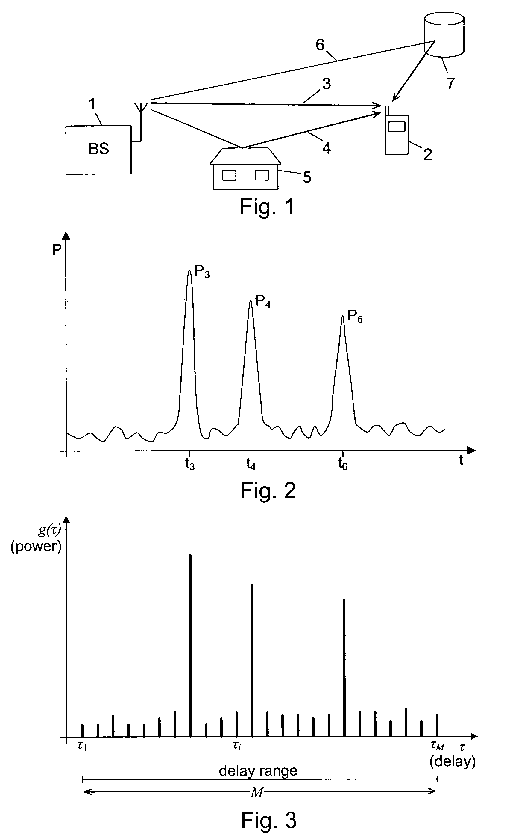
[0034]FIG. 1 shows a situation in which a base station 1 and a mobile station 2 of a wireless communications system communicate with each other. As an example, a signal transmitted from the base station 1 is received by the mobile station 2. However, the transmitted signal travels along multiple paths from the base station to the mobile station. In this case there is a direct and unobstructed propagation path 3, but in addition to this direct path, reflections from objects in the surroundings cause a number of indirect paths to exist. Two such paths are shown in the figure. One indirect path 4 is reflected from a house 5, while another path 6 is caused by reflection from another building 7.

[0035]Since the part of a signal transmitted via one of the indirect paths 4 and 6 has to travel a longer distance to arrive at the mobile station 2, compared to the part of the signal travelling via the direct path 3, multiple instances of the same signal will be received by the mobile station 2 ...


PUM


Abstract

Multipath components of transmitted data symbols are received with individual delays and processed by a RAKE unit having a number of fingers. A delay profile is calculated, and delay values for peaks detected therein are determined. A number of peak delay values (P<SUB>A1< / SUB>, P<SUB>A3< / SUB>, P<SUB>A4< / SUB>, P<SUB>A5< / SUB>) representing the largest peaks for the profile are pre-selected, and for each of them a signal-to-interference ratio for delay values in an interval around the pre-selected peak delay value is calculated. In each interval the delay value having the highest signal-to-interference ratio is selected and provided to the RAKE unit with each selected delay being assigned to a RAKE finger. Hereby the ability to select correct and accurate path delays can be improved also in time critical processes, where filtering of the delay profiles over several frames is not possible, because quite accurate delay values can be provided shortly after wake-up of the receiver.

Description

TECHNICAL FIELD OF THE INVENTION [0001]The invention relates to a method of receiving digital data symbols sent from a transmitter through a transmission channel of a communications network, in which individual multipath components of a transmitted data symbol are received with individual delays, and wherein received signals are processed by a RAKE unit having a number of fingers, the method comprising the steps of calculating a delay profile from a set of received pilot signals; and determining delay values for peaks detected in the delay profile. The invention further relates to a receiver for coded digital data symbols, and to a corresponding computer program and computer readable medium.DESCRIPTION OF RELATED ART [0002]In wireless communications systems the physical channel between a transmitter and a receiver is typically formed by a radio link. As an example, the transmitter could be a base station, and the receiver could be a mobile station, or vice versa. In most cases the t...

Claims


Application Information

Patent Timeline
IPC IPC(8): H04B1/707
CPCH04B1/7117H04B1/7113
Inventor WANG, XIAOHUI
Owner TELEFON AB LM ERICSSON (PUBL)
Learn More