
Hollow sphere metal oxides

a metal oxide and hollow sphere technology, applied in the field of hollow spheres and nanofoams, can solve the problems of sacrificial templates, long process time, and difficulty in maintaining the stability of nanocapsule suspensions, and achieve the effects of reducing the number of sacrificial templates, high vacuum and temperature, and preventing the formation of sacrificial templates

Inactive Publication Date: 2008-09-04
STC UNM
View PDF16 Cites 7 Cited by
  • Summary
  • Abstract
  • Description
  • Claims
  • Application Information

AI Technical Summary

Problems solved by technology

Fast disintegration and easy degradation of the nanocapsule shells after oral or parenteral administration and the difficulty with maintaining the stability of nanocapsules suspensions impede its medical applications and industrial development.
Fabrication via vapor-solid interfacial reaction such as laser ablation, molecular beam epitaxy, and chemical vapor deposition requires long process time, and high vacuum and temperature.
The sacrificial templates or surfactants, however, have to be removed by time consuming high temperature calcination or solvent extraction, and most of times the removal leaves behind cracks, defects, or carbonaceous impurities with the hollow nanospheres.
Furthermore, the engaged toxicity / pollution by the surfactants and solvents to the drug or target biological medium precludes their usage in the applications.
Aerosol assisted evaporation induced self assembly (EISA) has been successfully applied to make ordered core shell nano structures Although metal oxide nano hollow spherical particles can be formed by thermal decomposition and succeeding surface gelation via aerosol pyrolysis, the method can not be applied to fabricate hollow spherical titania or germania from their highly reactive precursors without templating and / or controlling the interfacial diffusion of reactant molecules.
To encapsulate heat sensitive biological materials the fabrication temperature is limited.

Method used


Image

  • Hollow sphere metal oxides
  • Hollow sphere metal oxides
  • Hollow sphere metal oxides

Examples


Embodiment Construction

[0016]Reference will now be made in detail to the present embodiments, examples of which are illustrated in the accompanying drawings. Wherever possible, the same reference numbers will be used throughout the drawings to refer to the same or like parts.

[0017]Notwithstanding that the numerical ranges and parameters setting forth the broad scope of the invention are approximations, the numerical values set forth in the specific examples are reported as precisely as possible. Any numerical value, however, inherently contains certain errors necessarily resulting from the standard deviation found in their respective testing measurements. Moreover, all ranges disclosed herein are to be understood to encompass any and all sub-ranges subsumed therein. For example, a range of “less than 10” can include any and all sub-ranges between (and including) the minimum value of zero and the maximum value of 10, that is, any and all sub-ranges having a minimum value of equal to or greater than zero an...


PUM

PropertyMeasurementUnit
diameteraaaaaaaaaa
residence timeaaaaaaaaaa
thicknessaaaaaaaaaa

Abstract

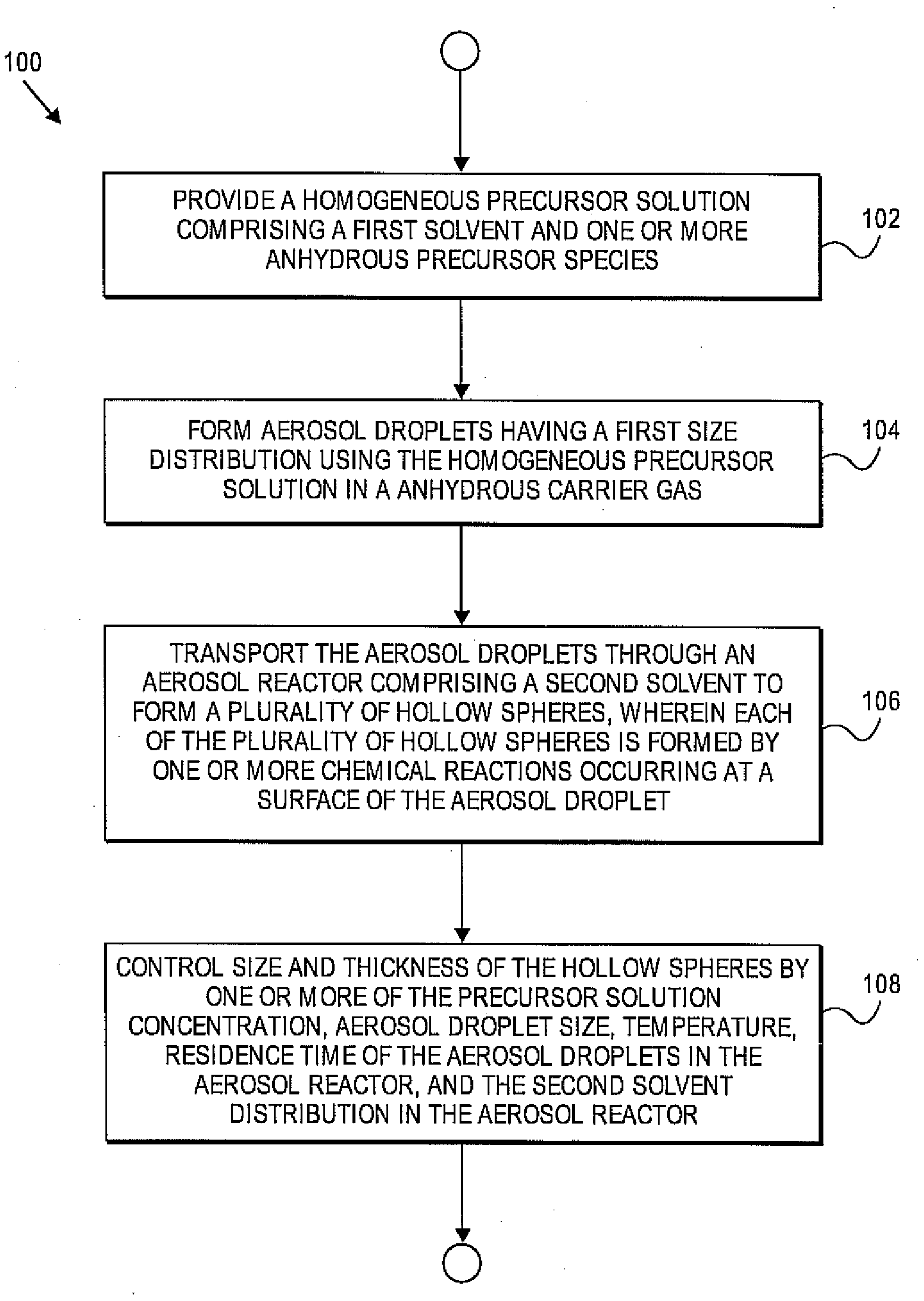
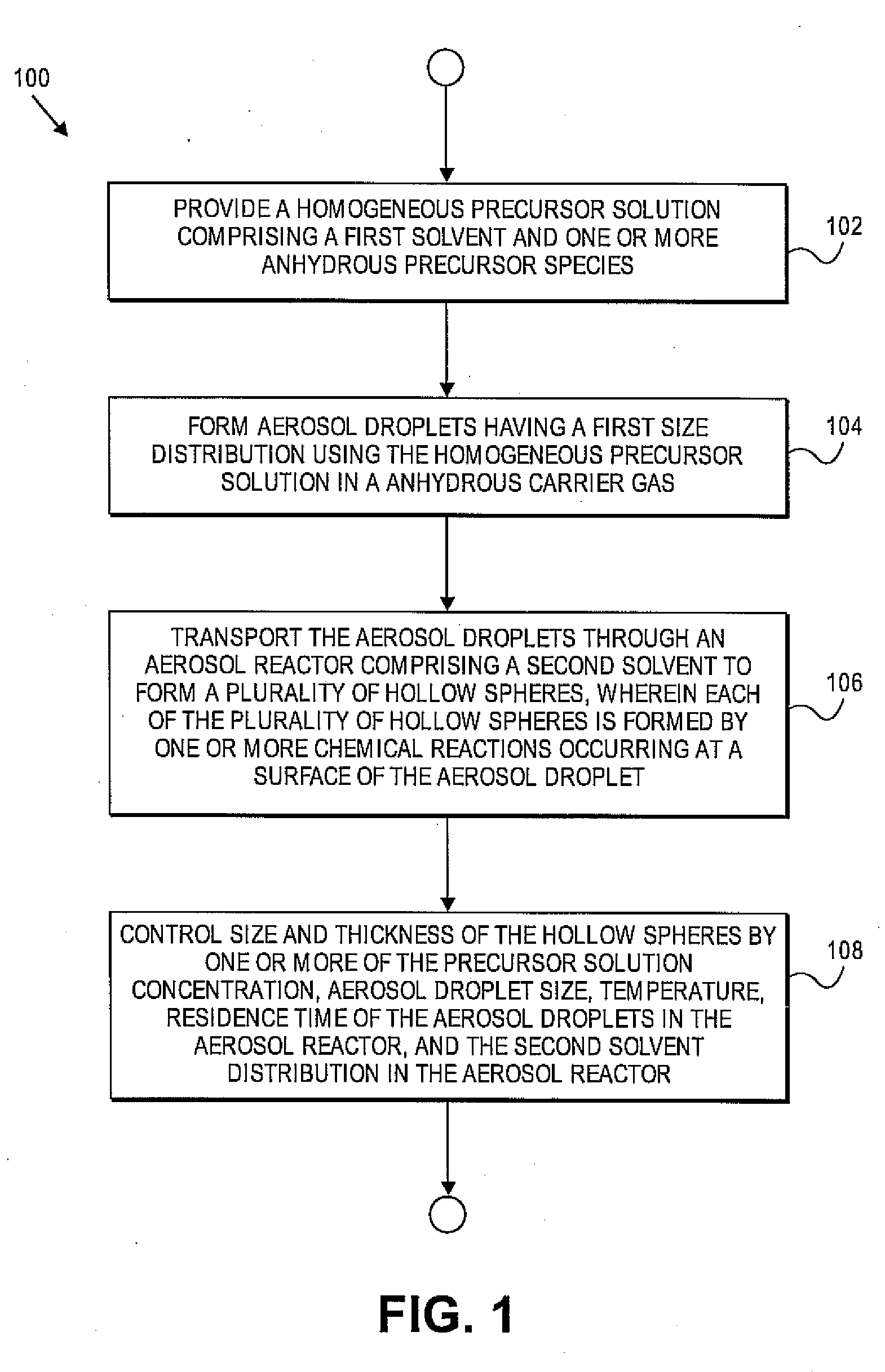
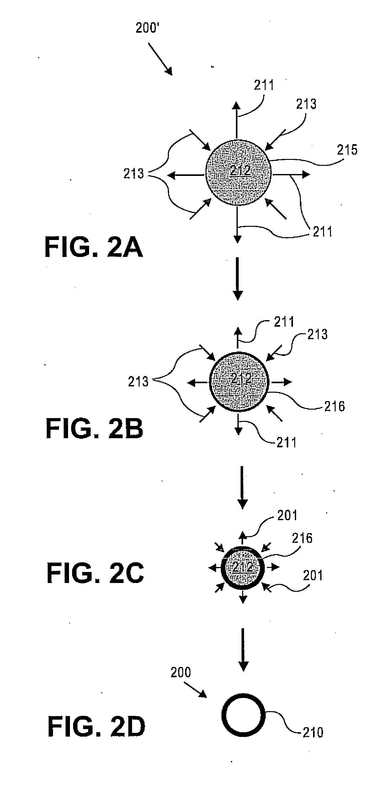
In accordance with invention, there are methods for fabricating hollow spheres and nanofoams. The method for making hollow spheres can include providing a homogeneous precursor solution including a first solvent and one or more anhydrous precursor species and forming aerosol droplets having a first size distribution using the homogeneous precursor solution in an anhydrous carrier gas. The method can also include transporting the aerosol droplets through an aerosol reactor including a reactant to form a plurality of hollow spheres, wherein each of the plurality of hollow spheres can be formed by one or more chemical reactions occurring at a surface of the aerosol droplet. The method can further include controlling size and thickness of the hollow spheres by one or more of the precursor solution concentration, aerosol droplet size, temperature, residence time of the aerosol droplets in the aerosol reactor, and the reactant distribution in the aerosol reactor.

Description

CROSS REFERENCE TO RELATED APPLICATION[0001]This application claims priority to U.S. Provisional Patent Application Ser. No. 60 / 854,933 filed on Oct. 27, 2006, the disclosure of which is incorporated by reference herein in its entirety.FEDERALLY SPONSORED RESEARCH[0002]The present invention was made with government support under Grant No. NSF NIRT EEC0210835 awarded by the National Science Foundation and Grant No. AFOSR-MURI / UVA #SC GG10306113743 awarded by the United States Air Force. As a result, the government may have certain rights in this invention.FIELD OF THE INVENTION[0003]The present invention relates to hollow spheres and nanofoams and, more particularly, to methods for fabricating hollow sphere structures and nanofoams.BACKGROUND OF THE INVENTION[0004]Nano- or submicron- sized hierarchic structures such as hollow spheres and capsules have been attracting increasing attention, owing to their wide applications in drug delivery, low dielectric constant substrates, chemical ...

Claims


Application Information

Patent Timeline
Patent Type & Authority Applications(United States)
IPC IPC(8): B22F9/16B01J2/04
CPCB01J13/0095B01J13/02B22F3/1112B22F2001/0029B22F2998/00B22F2999/00B22F1/0018B22F9/22B22F2201/013B22F1/0549B22F1/054
Inventor JIANG, XINGMAOBRINKER, CHARLES JEFFREY
Owner STC UNM
Learn More