
Heat Transfer Device and Manufacturing Method Thereof Using Hydrophilic Wick

Inactive Publication Date: 2008-09-04
CELSIA TECH TAIWAN INC
View PDF7 Cites 100 Cited by
  • Summary
  • Abstract
  • Description
  • Claims
  • Application Information

AI Technical Summary

Benefits of technology

[0015]Accordingly, the present invention is devised in consideration of the aforementioned problems and situations, and it is an object of the present invention to provide a heat transfer device having a new flat panel structure and ensuring high thermal conductivity at low cost, and a method of manufacturing the same.
[0016]It is a further object of the present invention to provide a heat transfer device having a flat panel structure, in which inner components in the device are made of a material having the capability to absorb water, thereby being able to eliminate the possibility of drying-out, and a method of manufacturing the same.
[0017]It is a still further object of the present invention to provide a heat transfer device having a flat panel structure, such that the heat transfer device can be manufactured by a simple method at low cost, and at high productivity since the defective proportion is low when the heat transfer devices are manufactured at mass production volumes. Further provided is a method for manufacturing the same heat transfer device.

Problems solved by technology

Recently, as the degree of integration of semiconductor chips, such as central processing units (CPU) and embedded chips, increases, cooling the semiconductor chips becomes a more important problem to solve.
However, known methods for cooling semiconductor chips, etc. mounted in the electronic components have the technical limits from structural and functional points of view, in particular from the aspects of packaging and cooling fan technologies.
First, manufacturing the heat pipe is difficult and complex because the heat pipe has a complex inner structure.
Second, since the wick layer 24 is copper felt, the degree of contact between the inner surfaces of the outer casing and the wick layer 24 varies among locations of the wick layer 24, and fine passages formed in the wick layer 24, for generating capillary force, are irregular, so that the reproducibility of the heat transfer device is poor with respect to heat conductivity.
Third, since it is difficult to manufacture the copper felt to be thin, the wick layer is thick, so that the heat pipe is thick too.
Due to this problem, the heat pipe cannot be used as a heat transfer device for ultra-thin semiconductor devices.
Fourth, since the flow resistance is high, it is difficult to generate high capillary force.
First, it is not easy to manufacture the flat panel type heat transfer device, and mass production thereof is impossible because micro machining is needed to manufacture a thin and complex structure to be inserted between an upper plate and a lower plate.
However, it is difficult to precisely machine such micro structures, since the micro structures are so complex and are several millimeters thick, so that the micro structures can be mounted in the flat panel type heat transfer device.
In particular, mass production of such micro structures is more difficult since the structure is so much complex, thereby the machining process therefor is very difficult and machining errors can occur.
Nonuniform gaps caused by the machining errors result in drying out of the liquid phase coolant at the evaporation part, thereby causing fatal failure of the heat transfer device.
Accordingly, it is possible to break through the process limit of etching or machining when forming micro patterns on the flat plates, and it is possible to realize fine coolant passage having a diameter of several micro meters, which is difficult to realize by the processing method such as etching or machining.
However, the heat transfer device according to the third prior art has the following disadvantage.
However, such an extremely thin metal plate is difficult to handle and incurs high processing cost.
Accordingly, the manufacturing cost increases.

Method used


Image

  • Heat Transfer Device and Manufacturing Method Thereof Using Hydrophilic Wick
  • Heat Transfer Device and Manufacturing Method Thereof Using Hydrophilic Wick
  • Heat Transfer Device and Manufacturing Method Thereof Using Hydrophilic Wick

Examples


first embodiment

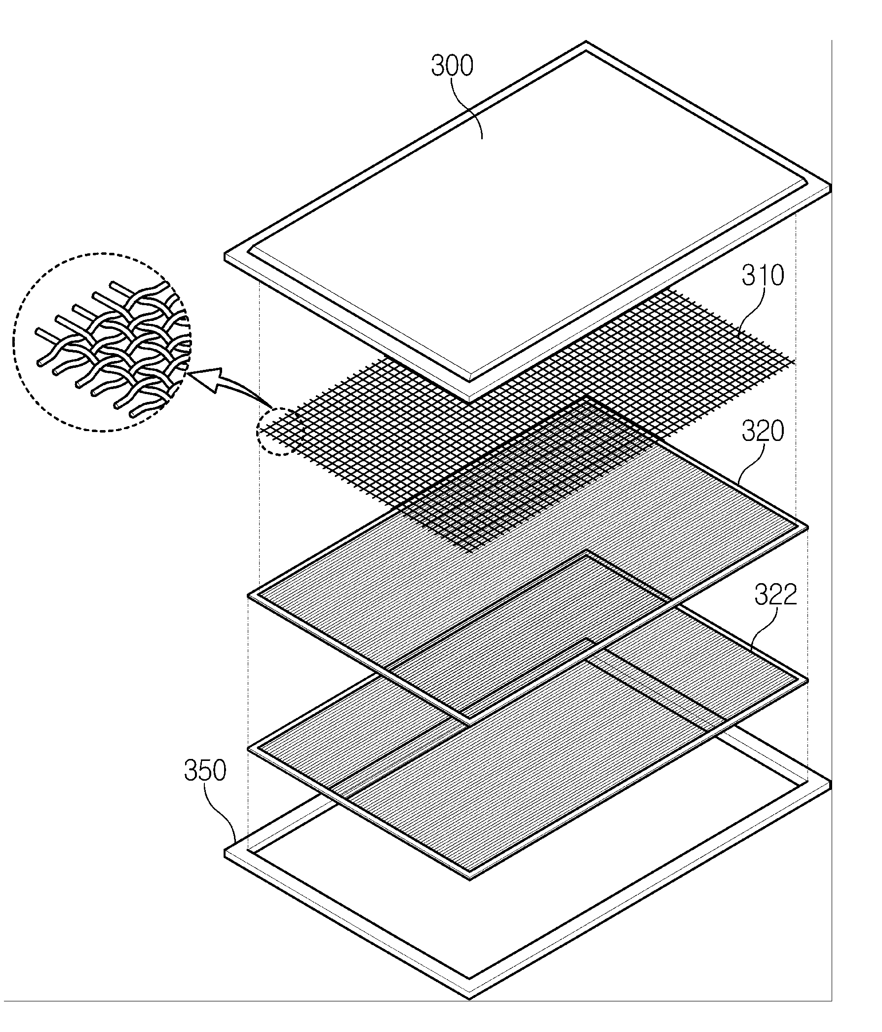
[0069]FIG. 6 illustrates a flat panel type heat transfer device using the above described hydrophilic wick structure, according to the invention. As shown in FIG. 6, the heat transfer device comprises a casing which comprises an upper plate 400 and a lower plate 450, two sheets of hydrophilic wick structures 420 disposed in the casing, and a support structure 410 such as a screen mesh which is also disposed in the casing. The hydrophilic structure is assembled with coolant loaded in the hydrophilic structure to wet the inner surface. In this case, it is not necessary that coolant be additionally injected between the upper plate 400 and the lower plate 450. Accordingly, the assembly process is simplified.

[0070]FIG. 7 is a sectional view of the heat transfer device shown in FIG. 6. When the heat transfer device is assembled, the support structure 410 brings the respective hydrophilic structures into close contact with the upper plate 420 and the lower plate 450.

[0071]FIG. 8 is a secti...

fifth embodiment

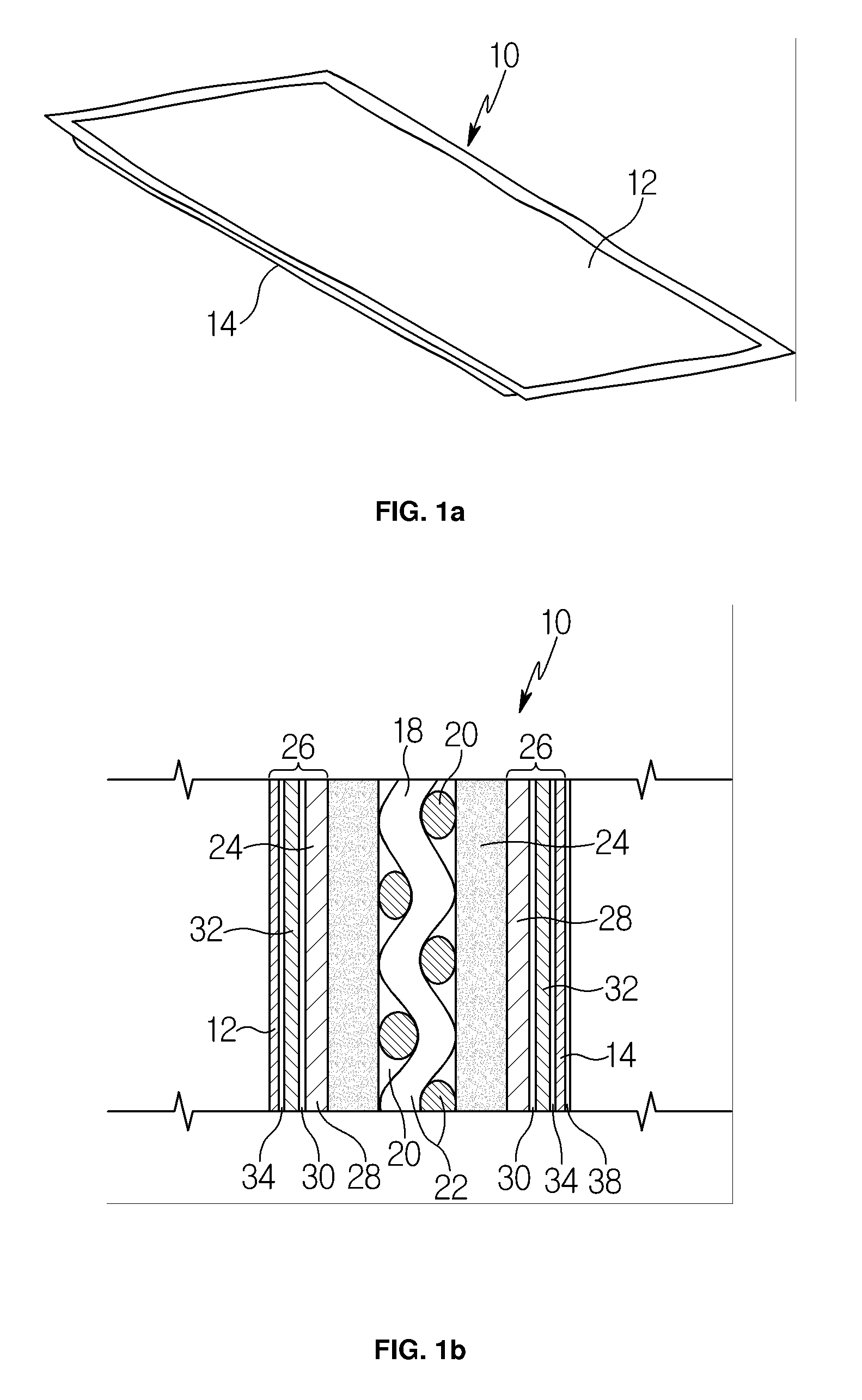
[0082]FIGS. 17a and 17b illustrate a heat transfer device according to the present invention. In the flat panel type heat transfer device, an upper plate 2400 and a lower plate 2450, together constituting a casing, are made of flexible polymer. The heat transfer device includes the above described hydrophilic wick structure 2420 to provide passages for vapor and liquid coolant, and a support structure 2410 to enable the hydrophilic wick structure 2420 to be in close contact with the upper surface of the lower plate 2450.

[0083]In the case of adopting the above described structure, the heat transfer device has high flexibility. Accordingly, the heat transfer device can be used for a heat source having a complex or three-dimensional structure. That is, it has wide applicability. However, since the gap between the upper plate and the lower plate must be maintained at a low pressure, as shown in FIG. 17a, the flexible upper plate 2400 can be brought into close in contact with the through...


PUM

PropertyMeasurementUnit
Thicknessaaaaaaaaaa
Thicknessaaaaaaaaaa
Thicknessaaaaaaaaaa

Abstract

Provided is a flat panel type heat transfer device for effectively dissipating heat generated from a heat source in contact with a casing, comprising the casing sealed and having a certain shape, a coolant loaded in the casing and undergoing phase transition, one or more flat panel type hydrophilic wick structures in contact with at least a portion of an inner surface of the casing, manufactured by aggregating fibers capable of absorbing the coolant, and providing a coolant passage leading the coolant to flow in a direction parallel to the inner surface of the casing, and one or more support structures, each having a plurality of through holes which provide coolant passages through which coolant in a vapor phase or a liquid phase flows, while supporting the hydrophilic wick structure such that the hydrophilic wick structure is in close contact with the inner surface of the casing, wherein the coolant fills a portion of a space in the casing and circulates in the space in a manner such that the coolant flows through the hydrophilic wick structure by means of capillary force generated in fine passages formed in the hydrophilic wick structure toward a relatively hot point, is evaporated by heat from a heat source, flows in a vapor phase toward a relatively low temperature point, condenses at the relatively low temperature point, flows back in a liquid phase to the relatively hot point, and repeats the cycle of evaporation and condensation.

Description

REFERENCE TO RELATED APPLICATIONS[0001]This is a continuation of pending International Patent Application PCT / KR2006 / 000037 filed on Jan. 5, 2006, which designates the United States and claims priority of Korean Patent Application No. 10-2005-0001028 filed on Jan. 6, 2005.FIELD OF THE INVENTION[0002]The present invention relates to a heat transfer device and a method of manufacturing the same. More particularly, the present invention relates to a heat transfer device for cooling a heat source by transferring heat from the heat source, such as electric components, semiconductor chips and display devices, to a relatively low temperature point.BACKGROUND OF THE INVENTION[0003]Recently, as the degree of integration of semiconductor chips, such as central processing units (CPU) and embedded chips, increases, cooling the semiconductor chips becomes a more important problem to solve. Further, electronic components, such as notebook computers, personal digital assistants (PDAs), and cellula...

Claims


Application Information

Patent Timeline
IPC IPC(8): F28D15/02B23P15/26
CPCF28D15/0233Y10T29/49366F28D15/046F28D15/02
Inventor KIM, JONG JINJANG, SUNG WOOKLIM, JONG SOOAN, YOUNG GILLEE, JEONG HYUNCHOI, JAE JOON
Owner CELSIA TECH TAIWAN INC
Features
  • Generate Ideas
  • Intellectual Property
  • Life Sciences
  • Materials
  • Tech Scout
  • Unparalleled Data Quality
  • Higher Quality Content
  • 60% Fewer Hallucinations
Learn More