Device for Irradiating Liquids with Uv Radiation in a Throughflow

a technology of liquid irradiation and throughflow, which is applied in the direction of flow control, filtration separation, lavatory sanitory, etc., can solve the problems of large space required, difficult to remove, and high cost of operation and maintenance, and achieve the effect of simplifying maintenan

a technology of liquid irradiation and throughflow, which is applied in the direction of flow control, filtration separation, lavatory sanitory, etc., can solve the problems of large space required, difficult to remove, and high cost of operation and maintenance, and achieve the effect of simplifying maintenan

US20080210884A1Inactive Publication Date: 2008-09-04DELTA UV SERVICE SYST

Image

  • Device for Irradiating Liquids with Uv Radiation in a Throughflow
  • Device for Irradiating Liquids with Uv Radiation in a Throughflow
  • Device for Irradiating Liquids with Uv Radiation in a Throughflow

Examples


Embodiment Construction

[0055]The invention will be described in detail in the following, on the basis of a preferred embodiment.

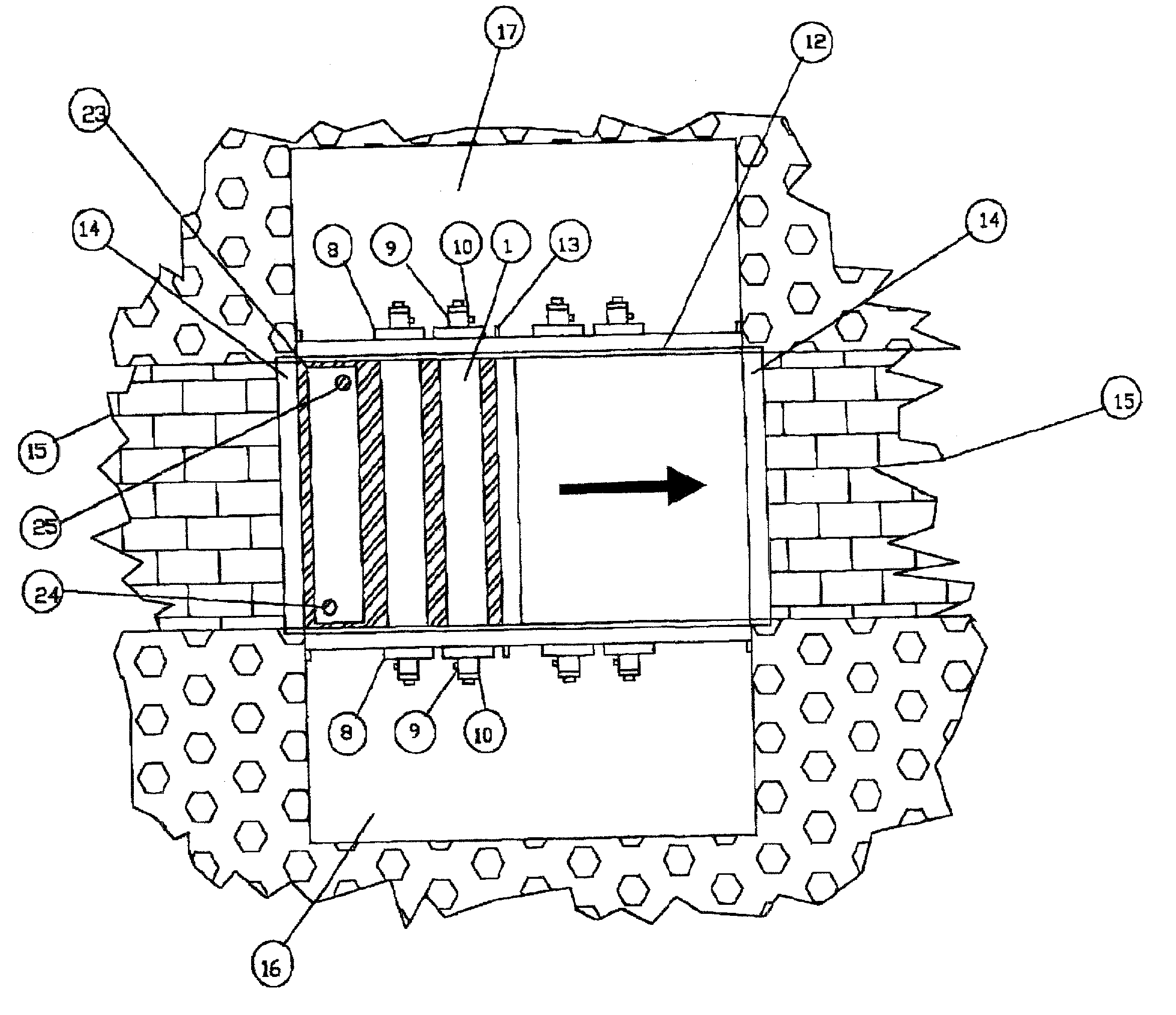
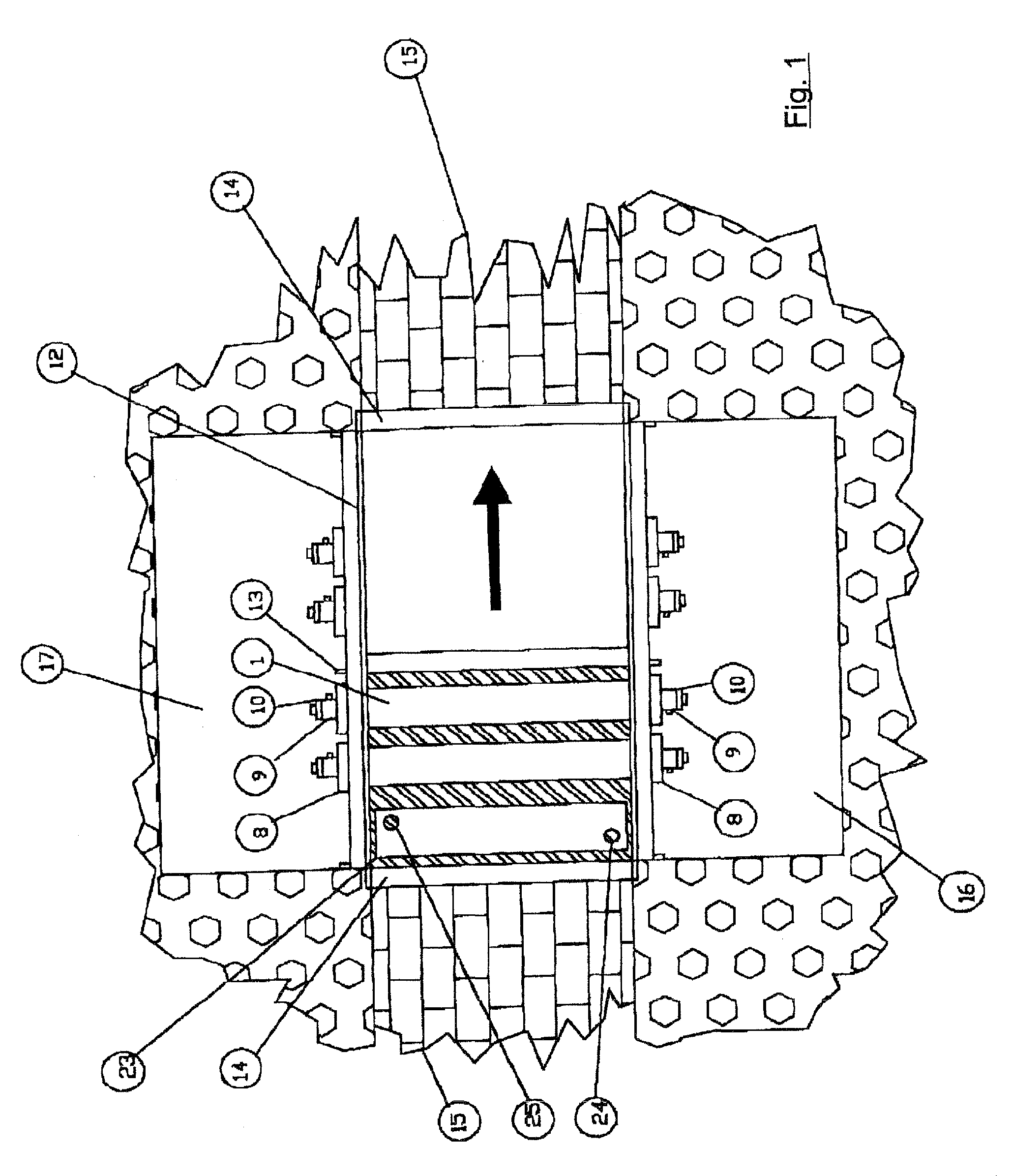
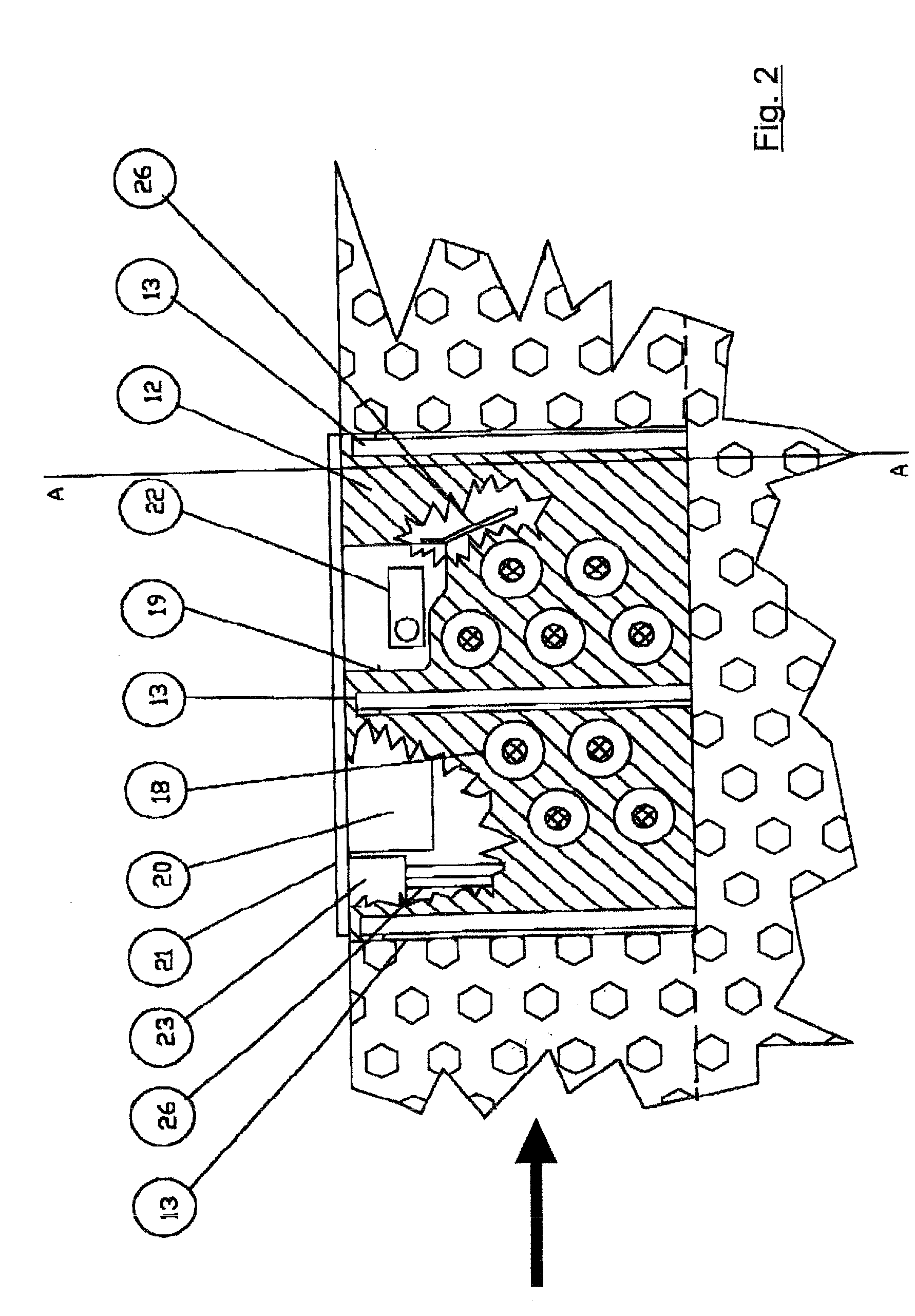
[0056]The device according to the invention is shown in top view in FIG. 1, in longitudinal section view in FIG. 2 and in cross-sectional view against the direction of flow in FIG. 3. The direction of flow of the absorbing liquid is indicated with an arrow, but is of no importance for the functionality of the device according to the invention. A U-shaped stainless steel wall 12, which is kept dimensionally stable by external stiffeners 13 and diagonal members 14 arranged above the surface of the liquid, is installed in channel 15. On each side there is a covered pit 16, 17, through which all electrical connections, control lines and pipes or hoses of the coolant circuit are led, and are accessible for maintenance purposes. In the two lateral vertical zones of the stainless steel wall 12 there are circular openings 18 in pairs opposite one another, into which the radiator assembli...


PUM

PropertyMeasurementUnit
diameteraaaaaaaaaa
diameteraaaaaaaaaa
diameteraaaaaaaaaa

Abstract

The invention relates to a device for irradiating an absorbing liquid, for example waste water to be disinfected, in a throughflow. Said device comprises at least two radiator units having one cylindrical UV radiation source and three concentric sheaths. A cooling medium for carrying off heat from the UV radiation source flows in a hollow space between the inner and the center sheath. The inventive device allows to use high-performance UV radiation sources and to evenly irradiate the zones of irradiation and prevents floating particles from settling down on the radiator units.

Description

FIELD OF THE INVENTION[0001]The invention relates to a device for irradiating absorbing liquids, for example wastewater that is to be disinfected, with UV radiation.PRIOR ART[0002]Devices for treating sewage treatment plant effluent for the purpose of reducing the germ count have long been known. The underlying research was published in 1984 by Scheible et al. in the publications of the Environmental Protection Agency with the title “Ultraviolet Disinfection of Waste Waters from Secondary Effluent and Combined Sewer Overflows”. Various concepts of disinfection of sewage treatment plant effluent using UV radiation were investigated in detail both theoretically and practically in the course of this research, and conclusions were drawn from it. Furthermore, requirements were formulated for the design and operation of a UV installation for wastewater disinfection. The following special characteristics of the medium (wastewater) were taken into account:[0003]high microbiological loading ...

Claims


Application Information

Patent Timeline
04 Sep 2008
Publication
US20080210884A1
IPC
B01J19/12; G01N23/10
CPC
A61L2/10; C02F1/325; C02F2303/04; C02F2201/326; C02F2201/3227; Y10S422/906
Inventors
EGBERTS, GERHARD