
High-frequency pneumatic loudspeaker for audio broadcasting

a high-frequency pneumatic and loudspeaker technology, applied in the field of loudspeakers, to achieve the effect of high sensitivity, easy deflection, and raised sensitivity of airstream modulation

Inactive Publication Date: 2008-09-04
BEIJING WAVE ENERGY TECH DEVMENT
View PDF1 Cites 12 Cited by
  • Summary
  • Abstract
  • Description
  • Claims
  • Application Information

AI Technical Summary

Benefits of technology

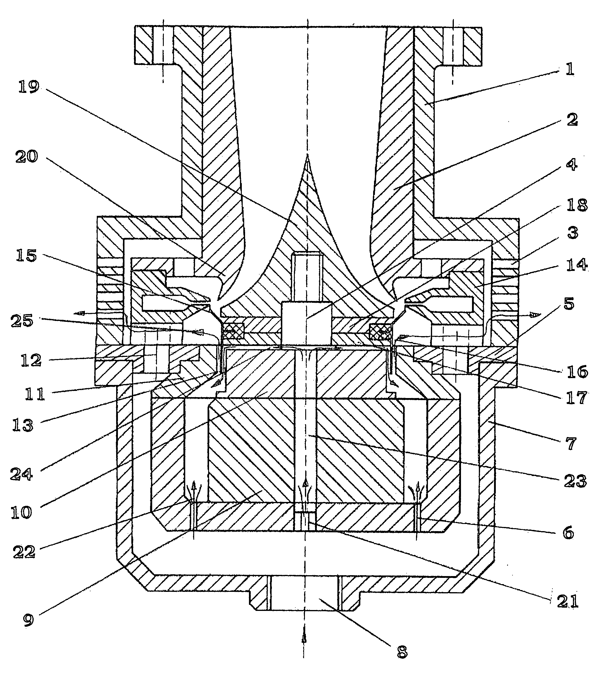
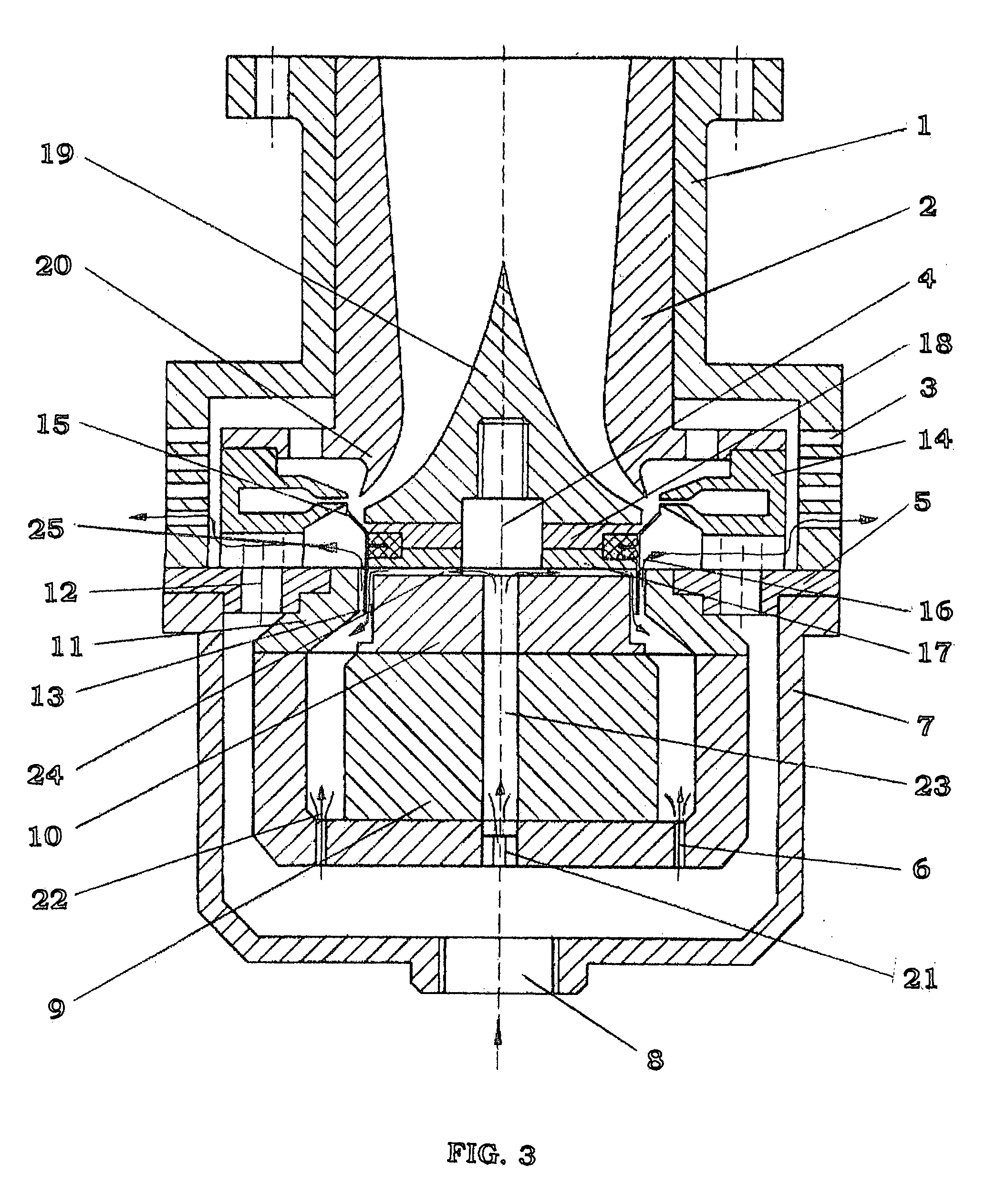
[0012]In consideration of the above, an object of the present invention is to provide a high-frequency pneumatic loudspeaker for sound broadcasting, which overcomes the defects of the prior art and which modulates the passage area while at the same time altering the direction of the jet, has the advantages of both the passage area modulation by a sleeve air valve and the airstream direction modulation by jet obstruction, reduces airstream consumption so as to improve air-sound conversion efficiency, and improves structures of annular flow-splitter, voice coil and leads. A high-frequency pneumatic loudspeaker for sound broadcasting of the present invention is also added with a cooling system. Thus, a high-frequency pneumatic loudspeaker for sound broadcasting of the present invention has improved high-frequency modulation sensitivity, operation stability, and / or extended fault-free operation time. It can be practically used for large area, long distance or high sound intensity broadcasting.
[0013]An embodiment of the present invention proposes a high-frequency pneumatic loudspeaker for sound broadcasting, which comprises a housing formed by an upper housing body and a lower housing body; the upper end of the upper housing body is opened; the side of the upper housing body is provided with silencer exhaust holes; the central portion of the lower end of the lower housing body has an air inlet port; a supporting plate is arranged between the upper and lower housing bodies and divides the internal space of the housing into an upper portion and a lower portion, which communicate with each other by an air channel. In the upper housing body, a throat canal, a central cone, an annular nozzle, an obstructing ring, and a voice coil and its leads are provided; the lower end of such a throat canal forms an annular flow-splitter; the inner side of the flow-splitter and the outer wall of the central cone form a throat channel; a lower plate and an upper plate and a rubber ring hold the obstructing ring and the voice coil in position; a magnet and inner and outer magnetic poles connected with the magnet are mounted in the lower housing body; the voice coil is arranged in a magnetic gap between the inner and the outer magnetic poles; a high-pressure air chamber is formed within the space between the outer magnetic pole and the lower housing body; high-pressure airstream enters into the high-pressure air chamber from the air inlet port and enters into the annular nozzle through a through-hole on the supporting plate; wherein a gap is provided between the obstructing ring and the end of the annular nozzle, and said gap avoids friction between the obstructing ring moving upward and downward and the end of the annular nozzle.

Problems solved by technology

These loudspeakers have wide range of frequency, so they can clearly broadcast various audio signals, but their single-unit acoustic power is limited.
When broadcasting in greater power is needed, it is usually necessary to combine a plurality of loudspeakers; even so, it is still not possible to meet the requirements of large area, long distance or high sound-intensity broadcasting.
But the frequency range of a pneumatic loudspeaker is narrow and can hardly be over 2,500 Hz, so its sound definition is bad.
At a distant location, as HF components attenuate more, definition is low and it is hard for a listener to hear clearly.
Thus, it has difficulty in being used for large-area, long-distance or high sound-intensity broadcasting.
And, to effectively modulate an airstream, it is necessary to operate under the state of big amplitude, and the present pneumatic loudspeakers cannot work for a long time without failure; so it is hard for them to be used in audio broadcasting of high sound-intensity.
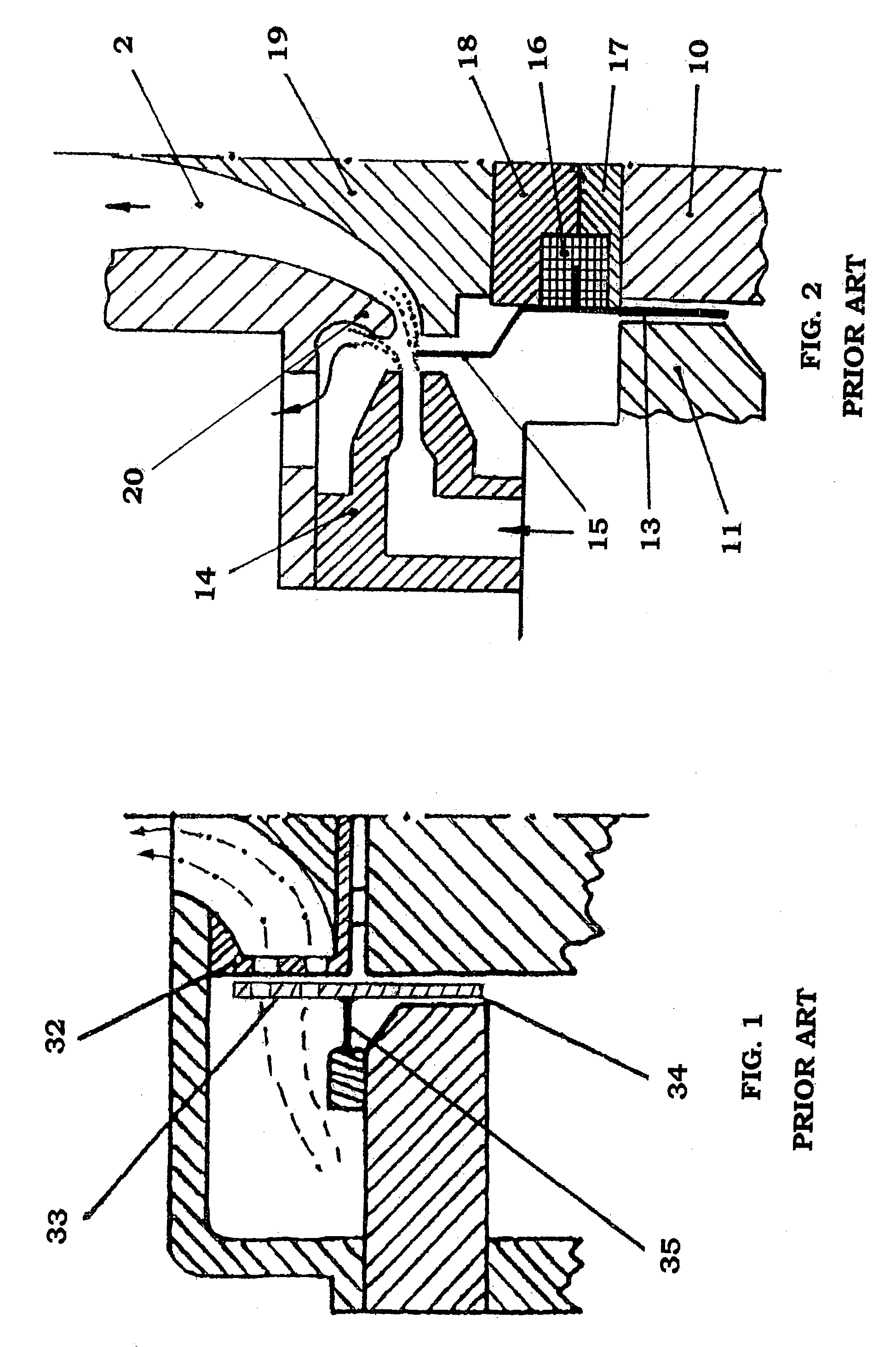
The movable ring 33 of this loudspeaker is arranged on the outside of the still ring, so an airstream pushes the movable ring 33 towards the still ring 32; in addition, since the gap between the movable and still rings is very small, the area of contact is big, although the amount of air to be consumed is reduced; thus, a relatively strong frictional force is generated, which tends to result in damage or blockage.
1) The loudspeaker modulates the direction of a jet by obstructing the jet to achieve the object of converting the high-pressure airstream to pressure wave; however, since the annular flow-splitter 20 at the lower end of the throat canal 2 has a blunt-circular shape, the sensitivity of high-frequency modulation is low; in addition, a relatively big gap exists between the obstructing ring 15 and the annular nozzle 14, resulting in significant air leak and low efficiency of airstream utilization. As shown in FIG. 2, at positive half-cycle of signal the obstructing ring 15 moves down to allow the jet to rush into the throat canal 2 to generate acoustic waves, while at negative half-cycle the obstructing ring 15 moves up to direct the jet towards the flow-splitter 20 having a front edge of blunt-circular shape, and as the obstructing ring moves further up the jet is directed by the flow-splitter 20 backward to enter the silencer exhaust hole and is exhausted into the atmosphere. As the obstructing ring 15 is for altering the direction of the jet, there is a relatively big separation between it and the nozzle 14, resulting in that a portion of the airstream leaks through the gap between the obstructing ring 15 and the nozzle 14, and this portion of the airstream has no contribution to the sound-generation and is wastefully dissipated. As the front edge of the flow-splitter 20 used has a blunt circular shape, its flow-splitter sensitivity at high-frequency is low and the high-frequency effect is not satisfactory. Although its air-sound conversion efficiency improved significantly as compared with a sleeve valve loudspeaker, the efficiency of airstream utilization of ZL92102274.3 still needs to be improved.
2) As the obstructing ring 15 is made by titanium, eddy displacement current will be generated in a strong magnetic field, resulting in damping effect and heat generation; the higher the frequency, the greater the damping effect and the heat generation. Thus, the modulation efficiency at high frequency is relatively low, the temperature during operation is very high, and long-time stable operation is difficult to be realized. As the obstructing ring 15 is made by titanium (specific weight: 4.5), it is still relatively heavy, its resonance frequency is still relatively low, and its amplitude at high-frequency is relatively small, and it can hardly realize effective modulation; therefore, its air-sound conversion efficiency at high-frequency is low, its high-frequency range is generally below 3,500 Hz, and its definition at a distant location is inferior.
3) The signal power applied during the operation of the signal coil—voice coil 13 is relatively high (usually in the range of 400-2,000 Watts or higher), resulting in generation of a relatively large amount of heat, and its heat-dissipating measure is not adequate. The temperature of the exhausted gas of a general industrial air-compressor can often reach 90C, plus the heat produced by the eddy current generated in the integral metal voice coil 13 moving in a strong magnetic field, the temperature of the obstructing ring 15 and the voice coil 13 at operation is high and they are easy to fail, so they can not sustain long-time and fault-free operation.
4) Since the amplitude of the obstructing ring 15 is relatively large, the leads of the voice coil 13 are made of knitted copper threads, which is subject to breaking-off due to fatigue, leading to operation failure.

Method used


Image

  • High-frequency pneumatic loudspeaker for audio broadcasting
  • High-frequency pneumatic loudspeaker for audio broadcasting
  • High-frequency pneumatic loudspeaker for audio broadcasting

Examples


Embodiment Construction

[0034]The present invention proposes a high-frequency pneumatic loudspeaker for sound broadcasting. Further description of its structure and operation principle will be made below with reference to the accompanying drawings and embodiments.

[0035]An overall structure of a high-frequency pneumatic loudspeaker of an embodiment of the present invention is shown inFIG. 3. A loudspeaker as shown in FIG. 3 comprises a housing formed by an upper housing body 1 and a lower housing body 7. The upper end of upper housing body 1 is opened for connecting with a trumpet or an acoustic radiator (not shown). Silencer exhaust holes 3 are provided on the side of upper housing body 1. An air-inlet port 8 is provided at the central portion of the lower end of lower housing body 7. A supporting plate 5 is arranged between upper housing body 1 and lower housing body 7 to divide the space inside the housing into an upper portion and a lower portion, which communicate with each other through an air channel...


PUM


Abstract

A high-frequency pneumatic loudspeaker for sound broadcasting is provided, and comprises a housing, silencer exhaust holes, air inlet port, supporting plate, throat canal, central cone, annular nozzle, obstructing ring, and a voice coil and leads. Lower and an upper press plates hold the obstructing ring and the voice coil in position, a magnet having inner and outer magnetic poles is connected therewith, wherein a small gap exists between the obstructing ring and the end of the annular nozzle. This provides the advantages of both air passage area modulation by a sleeve air valve and airstream direction modulation by jet obstruction, reduces airstream consumption, improves air-sound conversion efficiency, and improves structures of an annular air flow-splitter, voice coil and leads. A cooling system is provided to improve high-frequency modulation sensitivity, operation stability, and / or extended fault-free operation time.

Description

CROSS REFERENCE TO RELATED APPLICATION[0001]This application claims priority under 35 USC 119(a)-(f) from pending Chinese patent application number 200710064137.3, filed Mar. 2, 2007.FIELD OF THE INVENTION[0002]The present invention relates to a loudspeaker, particularly to a structural design of a high-frequency pneumatic loudspeaker for audio broadcasting.BACKGROUND OF THE ART[0003]Most of the loudspeakers presently used for broadcasting voice or music are electrodynamic loudspeakers. These loudspeakers have wide range of frequency, so they can clearly broadcast various audio signals, but their single-unit acoustic power is limited. Currently, the electrical power of a single loudspeaker is usually under 1,000 Watts. When broadcasting in greater power is needed, it is usually necessary to combine a plurality of loudspeakers; even so, it is still not possible to meet the requirements of large area, long distance or high sound-intensity broadcasting.[0004]A pneumatic loudspeaker use...

Claims


Application Information

Patent Timeline
Patent Type & Authority Applications(United States)
IPC IPC(8): H04R1/42
CPCH04R1/345H04R31/00H04R9/046H04R9/022
Inventor XI, BAOSHU
Owner BEIJING WAVE ENERGY TECH DEVMENT
Learn More