Medical imaging lens system, and method with high-efficiency light collection and collinear illumination

Inactive Publication Date: 2008-09-04
J FITNESS LLC
View PDF11 Cites 41 Cited by
  • Summary
  • Abstract
  • Description
  • Claims
  • Application Information

AI Technical Summary

Benefits of technology

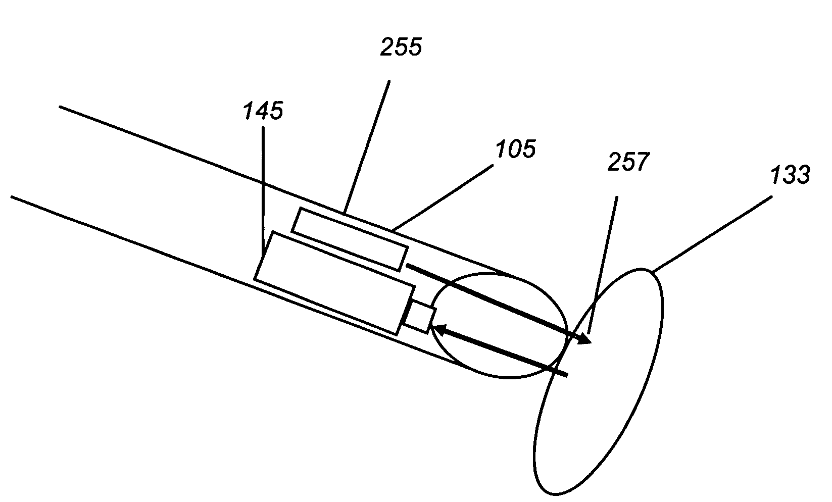
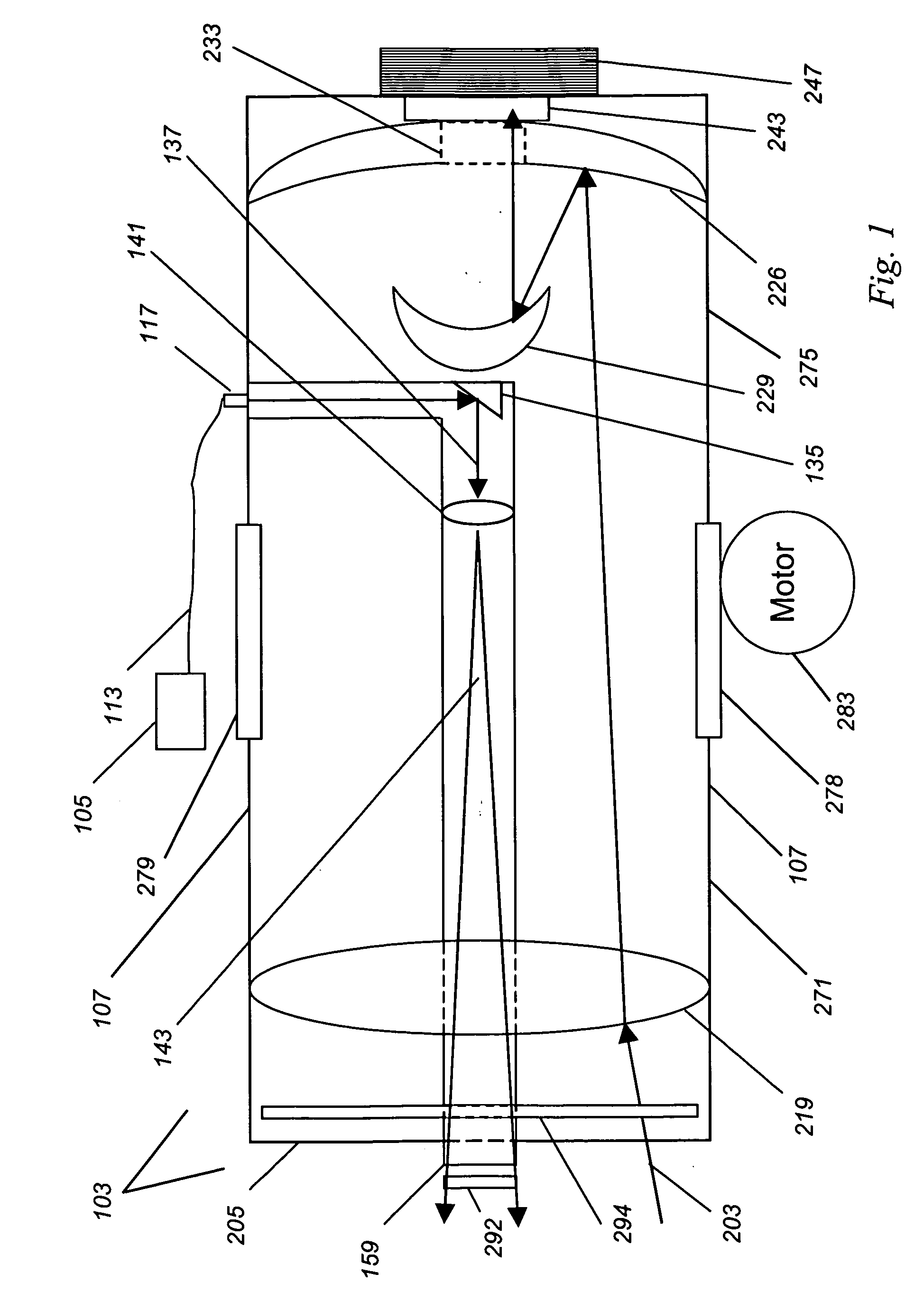
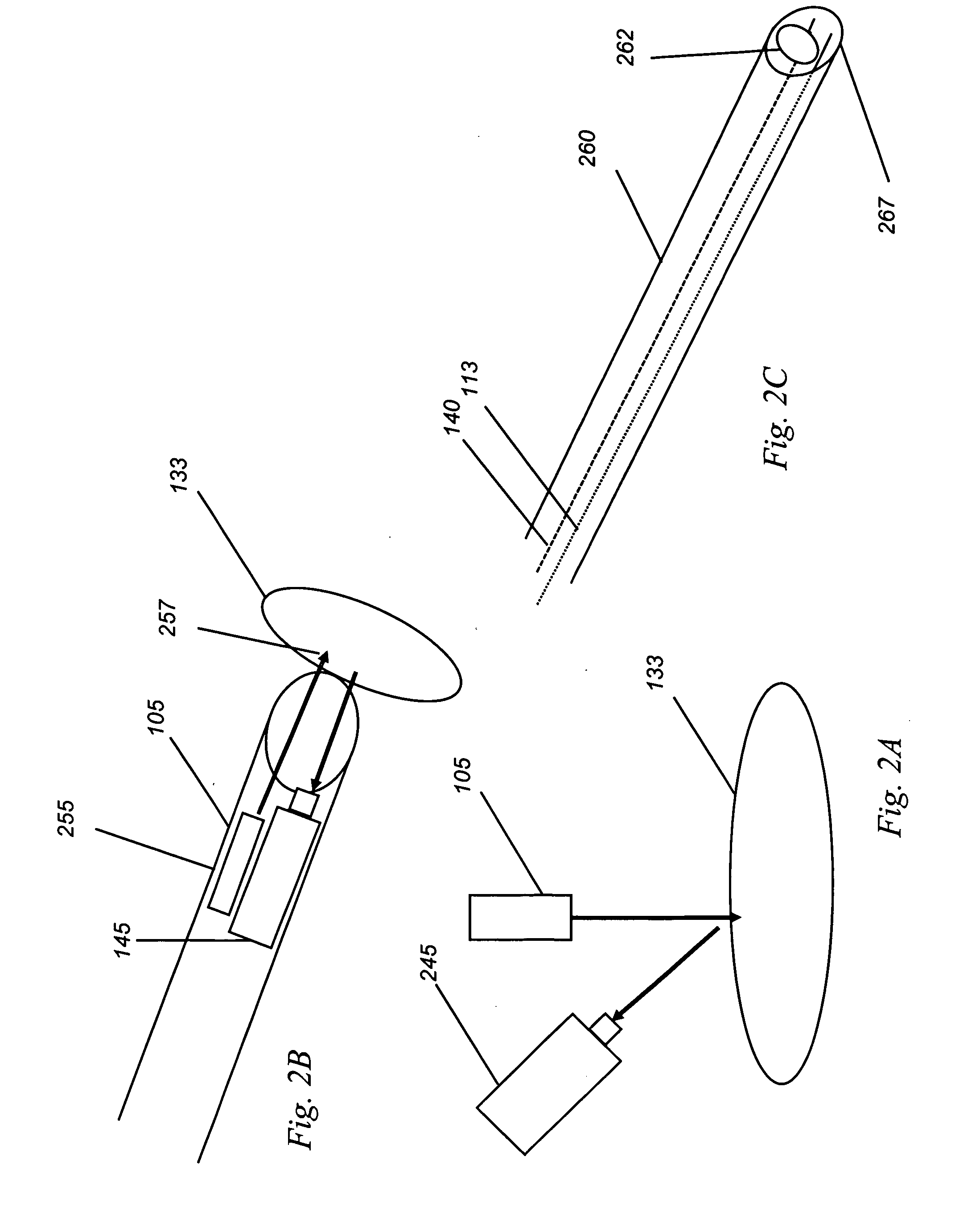
[0018]In some embodiments there is provided a focusing and imaging lens and illuminator for use in performing optical imaging on samples or living animals, with a higher throughput efficiency than with conventional lens sources, and with the option of collinear illumination, for the purpose of real-time biomedical optical imaging. In one example, the imaging system uses catadioptric lens and mirror system with a central collimated delivery beam, which can then be transmitted through free space to a sa

Problems solved by technology

However, such traditional light sources have significant native disadvantages, including that: (a) they tend to either be macro focus (focus at millimeters from a millimeter-wide subject) or zoom (focus many meters away and a large object), and focus poorly upon a surgical field that may be of intermediate size (i.e., 5-20 cm in diameter) and of intermediate distance (i.e., 50-100 cm from the lens), (b) they collect their light rather inefficiently, with a focus on spatial resolution above light-gathering, and (c) if the biological process being imaged requires light (such as a fluorescence process), they tend to have no seamlessly integrated method for providing light to the subject, and thus whenever the lens is moved, the light source must be separately readjusted and aligned.
Second, with respect to light gathering, optical contrast reporters tend to be weak emitters, and these emitters typically produce light in all directions—that is, relatively uniformly over a full 4π spherical angle—in the absence of mirrors or lenses.
This broad spatial emission typically makes the optical coupling of light from an optical contrast agent into a distant lens very inefficient.
However, only a portion of this light reaches the lens.
This makes for a very inefficient imaging, and for weak detection that requires strong signals in order to be detected.
In a surgical procedure, this is not acceptable.
Last, when attempting to combine an imaging or detection with feedback to a therapeutic, a lack of co-illumination makes it difficult to get real time feedback.
However none are suggested for biomedical optical imaging as combination light sources and imaging lenses, and their high-light collection and the option of co-illumination have not been cited nor exploited for biomedical optical imaging purposes, esp

Method used


Image

  • Medical imaging lens system, and method with high-efficiency light collection and collinear illumination
  • Medical imaging lens system, and method with high-efficiency light collection and collinear illumination
  • Medical imaging lens system, and method with high-efficiency light collection and collinear illumination

Examples


Example

Example 1

Improved Light Collection Using the Present Invention

[0088]One method to improve imaging efficiency is to improve the light collection efficiency—that is, to increase the fraction of target signal that reaches a detector.

[0089]In order to evaluate the impact of design considerations, we modeled the expected improvement in the efficiency of light collection achieved by altering various aspects of a collection lens design, and we then verified our model data using experiments. This model incorporated known features of light generation from tissue, the transmission characteristics of certain optical elements, and the like, and each aspect of the model was tested in the laboratory to confirm agreement of the predictions to those of measured results.

[0090]For this modeling, we assume that the lens focuses at 1 m with a field of view of 10-20 cm, and that the light source is a point of light, infinitesimally small, at the center of the imaging field. The highest theoretical limit...

Example

Example 2

Animal Imaging

[0095]In order to test the validity of the data generated using the model shown in Example 1, we constructed a working system for experimental tests, under U.S. Government support. This system was used to image dye in animal, as shown in FIG. 4. In FIG. 4A, mouse 520 can be seen from room light, while dye 531 contained inside mouse 520 is seen. In FIG. 4B, dye is seen at sites 543 and 546.

[0096]This demonstrates that the system is operative and functional in its intended use, namely room light imaging of dyes within living animals.

[0097]This type of lens can be used in targeted surgery, as is disclosed in WO 2000 / 68665, incorporated by reference in full into this disclosure. One example is mounting the camera over an auxiliary dissection for breast cancer to look at sentinel lymph nodes. In this case, the dye could be injected into the skin, and the fluorescence imaged with the catadioptric lens and illumination system. The detection in this case could be from...


PUM


Abstract

We have discovered an improved lens system for biomedical optical imaging applications for collecting light from tissue with an improved efficiency and geometry, and for delivering collinear, pre-aligned illumination to a the sample, for the purpose of enabling imaging applications in which a catadioptric lens and mirror system (103) is used for light collection, and integrated collimating illumination optics and aperture (159) have been provided, has been constructed in accordance with the present invention to allow for high-efficiency light collection in operating room and radiology suite imaging geometries. The efficient collection of light from the collinear illumination, allows this lens system to operate at higher speeds and with improved ease-of-use, as well as to be integrated into a lens system (103), a medical probe (255), or a catheter (270). A medical system incorporating the improved device, and medical methods of use, are described.

Description

CROSS REFERENCE OF RELATED APPLICATIONS[0001]This application claims the benefit of and priority to U.S. Provisional Patent Application No. 60 / 904,591, entitled “Biomedical Imaging Lens and Systems with High-Efficiency Light Collection and Collinear Illumination”, filed Mar. 2, 2007, the disclosure of which is incorporated herein by reference in its entirety.[0002]This invention was made with United States Government support, contract nos. CA-083597, CA-88190, and CA-107908 awarded by the U.S. National Institutes of Health. The Government has certain rights in the invention.FIELD OF THE INVENTION[0003]The present invention relates generally to imaging devices and systems for providing a high efficiency of light delivery to biological organisms, tissues, or agents, and more particularly relates to the embedding of collinear illumination optics within a high-light-collection, low-numerical aperture lens of catadioptric design for the purpose of performing real-time in vivo planar or t...

Claims


Application Information

Patent Timeline
IPC IPC(8): A61B6/00
CPCA61B1/00188A61N5/062A61B1/0661A61B5/0059A61B5/0071A61B5/0075A61B5/0084A61B5/415A61B5/418A61B5/6848A61B17/3403A61B19/5202A61B19/5212A61B2017/2926A61B2019/5206A61B2019/521A61B2019/5219A61B2019/5221A61B2019/5291A61B1/043A61B90/30A61B90/361A61B2090/306A61B2090/309A61B2090/3616A61B2090/3618A61B2090/365
Inventor BENARON, DAVID A.PARACHIKOV, ILLIAN H.
Owner J FITNESS LLC
Why Eureka
Try Eureka