Reversible thermal thickening grease

a thermal thickening grease and reverse technology, applied in the direction of lubricant composition, fuel, thickener, etc., can solve the problems of affecting the heat removal of the package, the grease flow back into the gap, and the thermal grease is subject to being pumped out of the gap, so as to improve the fluid properties, reduce the flow, and increase the viscosity of the greas

Inactive Publication Date: 2008-09-11
GLOBALFOUNDRIES INC
View PDF2 Cites 2 Cited by
  • Summary
  • Abstract
  • Description
  • Claims
  • Application Information

AI Technical Summary

Benefits of technology

[0012]Accordingly, the following embodiments provide for the minimization of grease pump-out in a microelectronic package by improving the fluid properties through reversible thermal thickening. For instance, when temperature increases the grease becomes a pseudo-gel or highly viscous matrix, and when temperature decreases it recovers its original fluidity. Thus, at high microelectronic package temperatures when the grease is subjected to a compressive force, flow is minimized by an increase in the grease viscosity, while at low temperatures when decompression occurs, the grease reverts back to a fluid that can readily respond to the widening gap.

Problems solved by technology

In particular, thermal greases are subject to being pumped out of the gap with the repetitive expansion and contraction of the package that occurs with thermal excursions.
When the chip and package cools during chip idle or off state, the package contracts and there is a negative pressure in the gap that results in the grease flow back into the gap.
This effect is commonly referred to as grease pump-out which negatively impacts heat removal from the package.
Currently, there are no known methods or strategies of minimizing grease pump-out while retaining the grease fluidity with repetitive thermal stresses.
Though these gels overcome the problems associated with grease pump-out, the absence of fluidity in the system negatively impacts stress accommodation by the TIM.
It is commonly observed that gel TIMs fracture with tensile loading during package contraction in the cooling phase of the thermal cycle.

Method used


Image

  • Reversible thermal thickening grease
  • Reversible thermal thickening grease
  • Reversible thermal thickening grease

Examples


Embodiment Construction

[0046]A more complete appreciation of the disclosure and many of the attendant advantages will be readily obtained, as the same becomes better understood by reference to the following detailed description when considered in connection with the accompanying drawings.

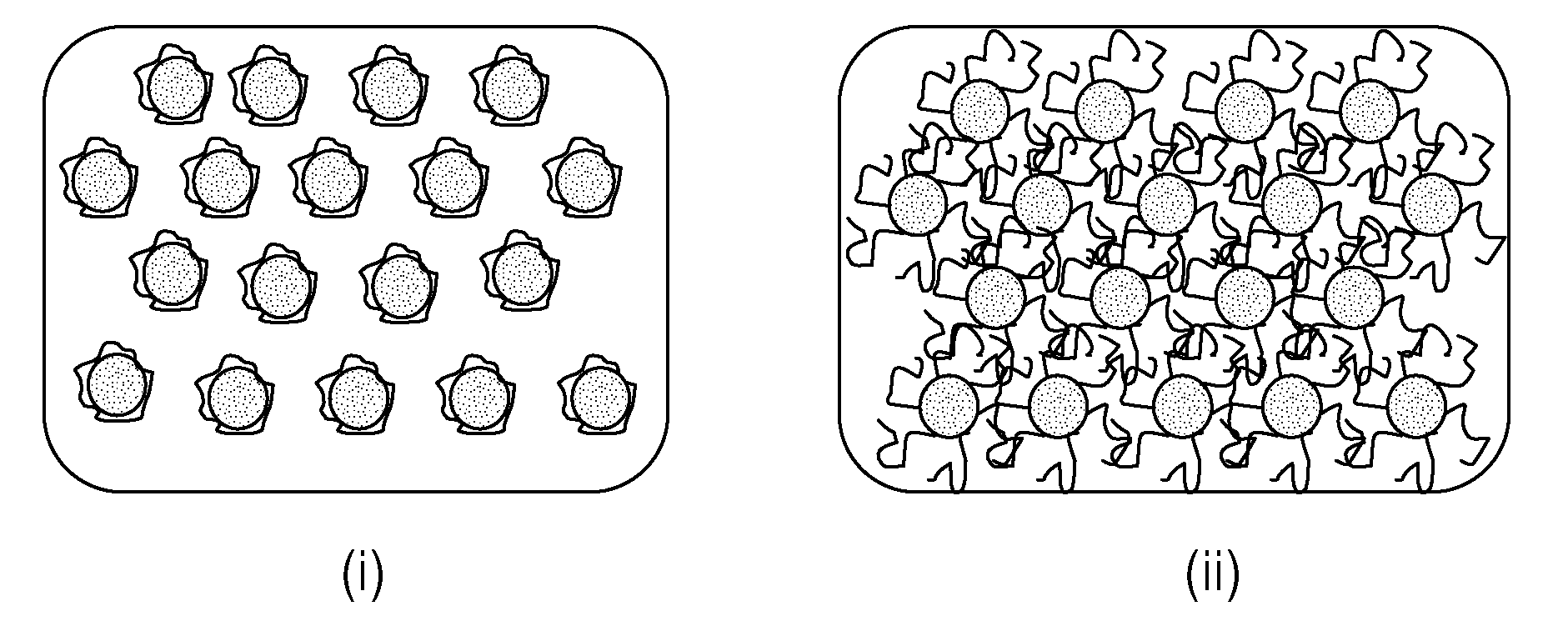
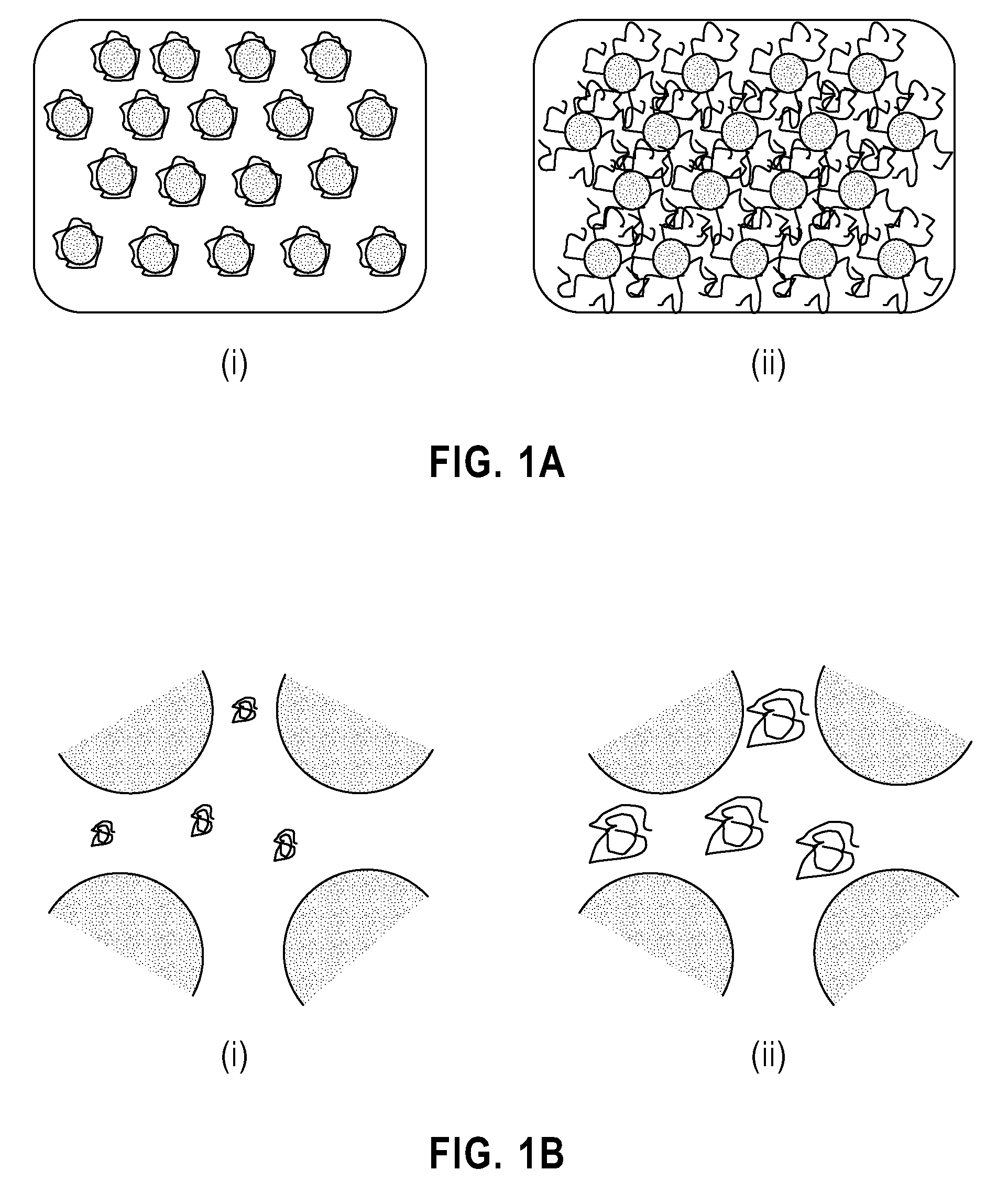
[0047]The filler particles used in the reversible thermal thickening grease (“thermal grease”) may be solid and formed of any shape. For example, the filler particles may be solid, may vary in size, and may be spheres, platelets, flakes, and / or fibers. The filler particles may also be ceramic, metallic, or carbon-based. For example, the filler particles may include, but are not limited to, silicon fillers, gold fillers, aluminum fillers, silver fillers, metal oxide fillers, metal nitride fillers, silicon carbide fillers, diamond fillers, carbon nanotube fillers, graphite fiber fillers, or combinations thereof. The volume fraction of the filler particles in the thermal grease may range from about 0.6 to about 0.9.

[0048]The...


PUM

PropertyMeasurementUnit
Theta temperatureaaaaaaaaaa
temperatureaaaaaaaaaa
temperaturesaaaaaaaaaa

Abstract

A reversible thermal thickening grease for microelectronic packages, in which the grease contains filler particles; at least one polymer; and a binder; in which the filler particles are dispersed within the binder, in which one or more segments of the at least one polymer may be attached to the filler particles prior to dispersion in the binder, and in which the polymer collapses at temperatures below a Theta temperature and swells at temperatures above a Theta temperature. During the operation of a microelectronic package, grease pump-out and air proliferation are minimized with use of the reversible thermal thickening grease, while grease fluidity is retained under repetitive thermal stresses.

Description

BACKGROUND[0001]1. Technical Field[0002]The disclosure relates to a reversible thermal thickening grease, especially for microelectronic packages, a method of making the reversible thermal thickening grease, and a microelectronic package containing the reversible thermal thickening grease. In particular, the disclosure relates to a reversible thermal thickening grease for microelectronic packages, in which the grease contains filler particles and a binder, in which one or more segments of at least one polymer may be attached to surfaces of the particles and / or included in the grease without attachment, such that the fluidity of the grease minimizes grease pump-out that leads to air in the chip-heat sink interface.[0003]2. Discussion of the Background[0004]Thermal greases have been used extensively for microelectronic flip-chip packages as thermal interface materials (TIMs) with a two-fold objective:[0005](i) to improve conduction of heat away from the chip; and[0006](ii) to provide ...

Claims


Application Information

Patent Timeline
Patent Type & Authority Applications(United States)
IPC IPC(8): C10M101/04H01L23/34
CPCC10M169/02C10M171/02H01L2924/0002C10M2201/0413C10M2201/053C10M2201/0613C10M2201/0623C10M2201/1006C10M2201/1023C10M2203/1025C10M2203/1045C10M2205/02C10M2205/04C10M2207/401C10M2209/084C10M2209/102C10M2209/103C10M2209/1033C10M2211/083C10M2217/044C10M2229/02C10M2229/025C10N2220/00C10N2220/082C10N2220/084C10N2220/086C10N2230/00C10N2230/02C10N2230/08C10N2240/20C10N2250/18H01L23/3737H01L2924/00C10N2020/00C10N2020/061C10N2020/063C10N2020/06C10N2030/00C10N2030/02C10N2030/08C10N2040/14C10N2050/14
Inventor FEGER, CLAUDIUSGELORME, JEFFREY D.IRUVANTI, SUSHUMNAKUMAR, RAJNEESHNNEBE, IJEOMA M.
Owner GLOBALFOUNDRIES INC
Why Eureka
Try Eureka