Protection of Secure Electronic Modules Against Attacks

a technology of electronic modules and protection against attacks, applied in the field of physical security cryptographic hardware modules, can solve the problems of affecting the complete removal of data, the inability to recover data or data preservation in memory devices, and the inability to completely remove sensitive data in the entire memory, so as to reduce the exposure to data imprinting in storage memory and the effect of fast data removal

Inactive Publication Date: 2008-09-11
IBM CORP
View PDF16 Cites 32 Cited by
  • Summary
  • Abstract
  • Description
  • Claims
  • Application Information

AI Technical Summary

Benefits of technology

[0010]The shortcomings of the prior art are overcome and additional advantages are provided through the provision of encrypting the sensitive data in secure storage volatile memory with a master key. This master key becomes the data that can be more confidently destroyed upon a tamper event. Since the amount of sensitive data has been reduced to the master key, active erasure can be used to provide faster more complete data removal within the tamper res

Problems solved by technology

The tamper response to penetration of physical enclosures must remove sensitive data within a period of time that makes breach of the enclosure and data retrieval or data preservation in memory devices highly unlikely.
This volatile memory device is used to store sensitive data in secure enclosures because the sensitive data in the entire memory can be destroyed in a relatively fast operation by removing power to the device when a tamper event occurs.
When the memory device or security module is subjected to low temperatures the electrical discharge (data destruction) of the memory cell upon power removal or grounding of the power supply takes longer.
Conversely, subjecting the memory device to higher voltage than the maximum specified operating voltage of the device for extended periods and/or subjecting the device to higher temperatures for long periods can cause preferential states to be ‘burned into’ the memory storage elements devices.
Therefore the tamper response becomes ineffective because the removal of power to the memory device may not affect the preferred states within the memory device that will be revealed when powered up.
However, temperature and voltage limit threshol

Method used


Image

  • Protection of Secure Electronic Modules Against Attacks
  • Protection of Secure Electronic Modules Against Attacks
  • Protection of Secure Electronic Modules Against Attacks

Examples


Embodiment Construction

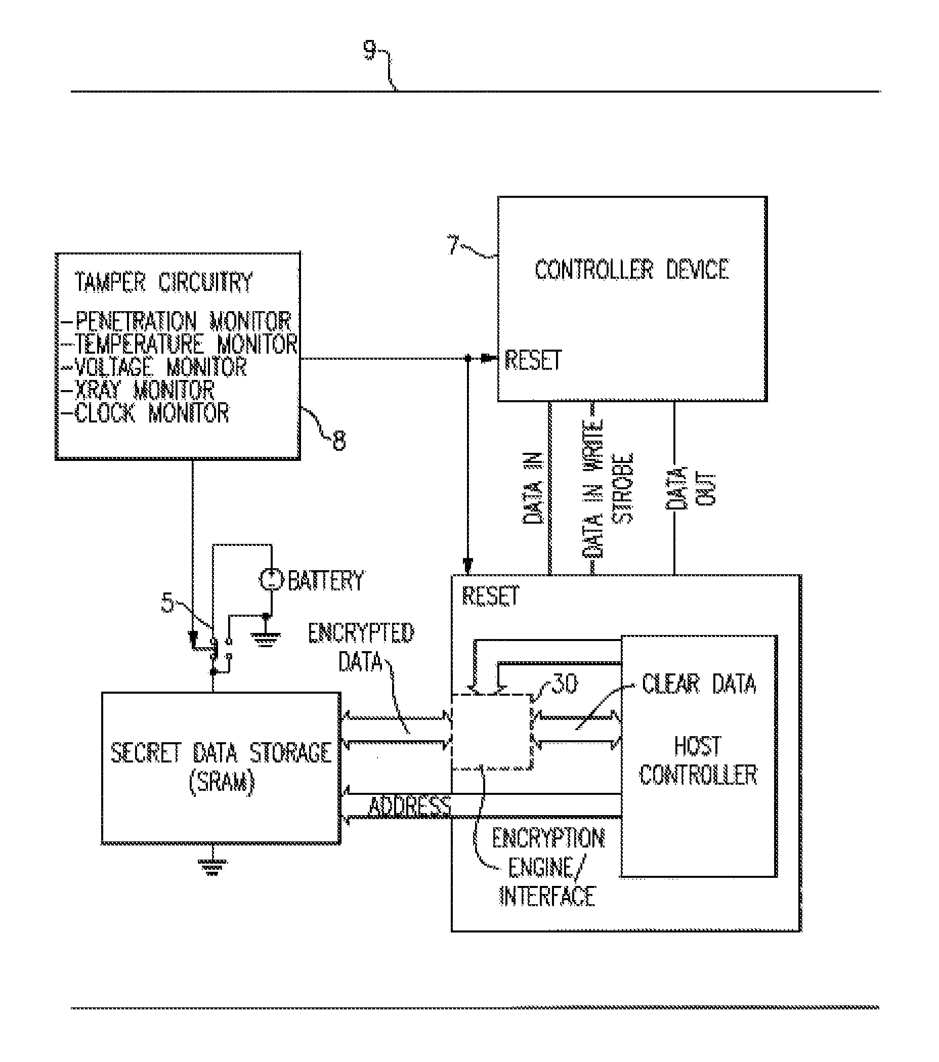
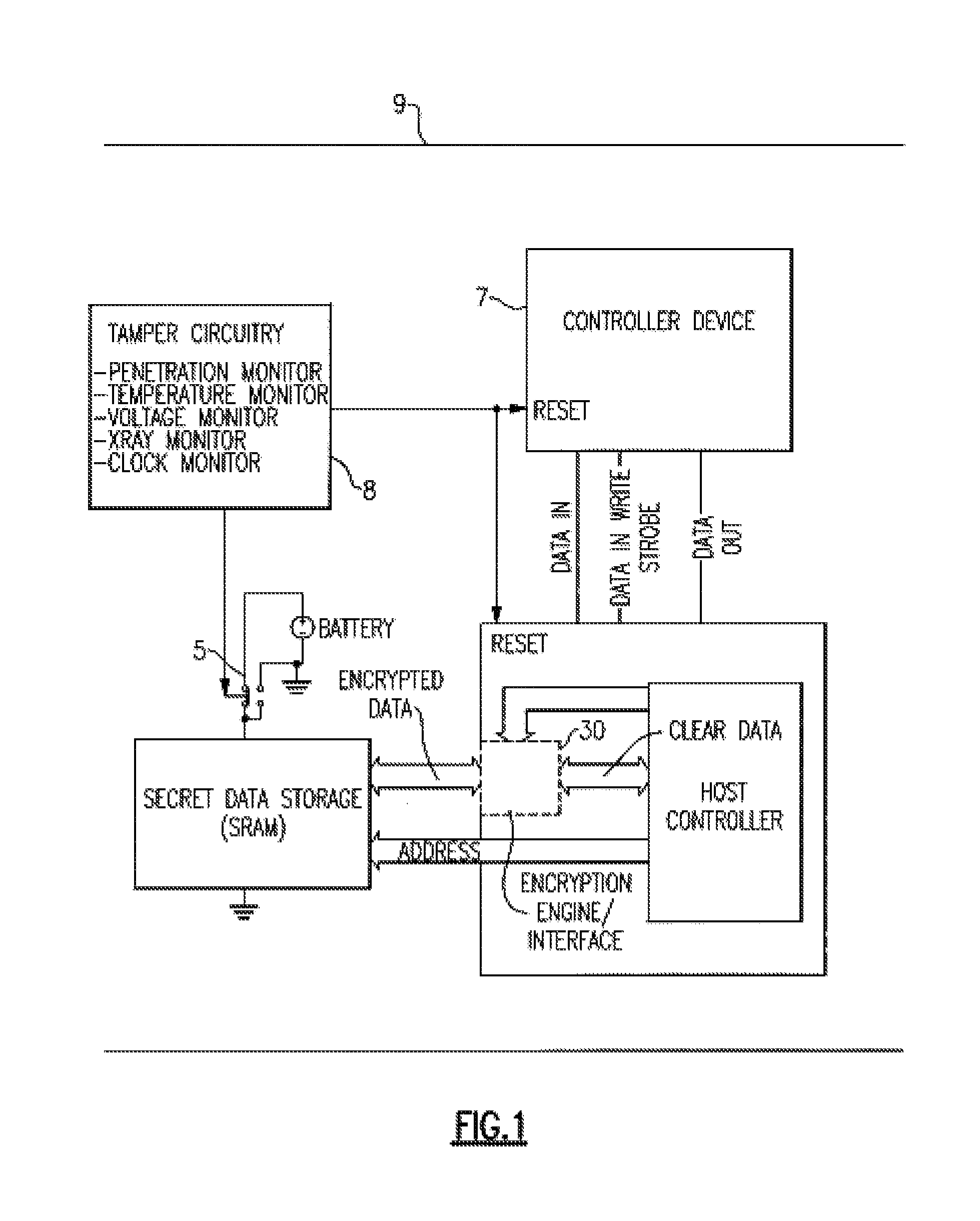
[0017]Turning now to the drawings in greater detail, it will be seen that FIG. 1 is directed to a memory system or security module 9 in accordance with the present invention which is operated within an electronically secure environment having a plurality of sensors designed to detect various forms of tampering as well as fluctuations in temperature, x-ray, voltage, and power fluctuations. Module 9 is thus located within this secure tamper respondent system. This module 9 provides the encryption of data secrets, active erasure upon a tamper event of the key(s) used to encrypt data secrets, and periodic inverting of the key(s) data used to encrypt data secrets. The system 9 includes a controller device 7 having a master key storage register 71 connected to an inverter 72 which periodically inverts or toggles the master key storage register 71. A more detaile illustration of the controller device is shown in FIG. 3. The system 9 may use either a software or hardware encryption engine o...


PUM


Abstract

A method and apparatus is disclosed for preventing the unintended retention of secret data caused by preferred state/burn in secure electronic modules. Sequentially storing the data, and its inverse on alternating clock cycles, and by actively overwriting it to destroy it, prevents SRAM devices from developing a preferred state. By encrypting a relatively large amount of secret data with a master encryption key, and storing said master key in this non-preferred state storage, the electronic module conveniently extends this protection scheme to a large amount of data, without the overhead of investing or actively erasing the larger storage area.

Description

FIELD OF THE INVENTION[0001]This invention relates to physically secure cryptographic hardware modules, and particularly to tamper response methods to protect sensitive data stored within the module.DESCRIPTION OF BACKGROUND[0002]Systems that provide physical security of sensitive data such as cryptographic keys typically require enclosures that contain the circuitry that stores and processes the sensitive data. U.S. Pat. No. 4,860,351—‘Tamper Resistance Packaging Protection of Information Stored in Electronic Circuitry’ describes how such a secure enclosure is implemented md is hereby incorporated in its entirety herein. The tamper response to penetration of physical enclosures must remove sensitive data within a period of time that makes breach of the enclosure and data retrieval or data preservation in memory devices highly unlikely. SRAM memory technology is frequently used for memory applications that store sensitive data in security modules. SRAM data remains stored in the mem...

Claims


Application Information

Patent Timeline
IPC IPC(8): G06F12/14
CPCG06F2221/2143G06F21/86
Inventor BUSCAGLIA, CARL U.CONDORELLI, VINCENZOGOTZE, KEVIN C.HADZIC, NIHADPLASS, DONALD W.VISEGRADY, TAMAS
Owner IBM CORP
Why Eureka
Try Eureka