Micro electro-mechanical system and method of manufacturing the same

a micro electromechanical and electromechanical technology, applied in the direction of microstructural technology, microstructural devices, basic electric elements, etc., can solve the problems of large excitation energy, difficult to stably manufacture a mems resonator with a narrow gap, and sticking phenomena, so as to prevent sticking of the movable part, stably form, and narrow the gap

Active Publication Date: 2008-09-18
LAPIS SEMICON CO LTD
View PDF0 Cites 80 Cited by
  • Summary
  • Abstract
  • Description
  • Claims
  • Application Information

AI Technical Summary

Benefits of technology

[0008]The present invention aims to provide a micro electro mechanical system that can be formed so as to prevent sticking of movable parts and includes a narrow gap, and a method of manufacturing the same.
[0012]According to the method of manufacturing the MEMS of the present invention, the at least one fixed electrode and the at least one movable electrode are formed so that a gap between the fixed electrode and the movable electrode is formed largely in an initial step. After removing the sacrifical film, the conducting film is formed on the fix electrode so that the gap has a design value. Therefore, it is possible to provide a micro electro mechanical system which can be stably formed so as to prevent sticking of the movable part and have a narrow gap.

Problems solved by technology

However, the MEMS resonator of FIG. 2B needs a large excitation energy due to its large mass.
Therefore, there is a possibility that sticking phenomena may occur due to surface tension of an etchant in a drying process after etching the sacrifical film.
Therefore, it is difficult to stably manufacture a MEMS resonator with a narrow gap such as the tuning folk structure as shown in FIG. 2C at a high yield rate.

Method used


Image

  • Micro electro-mechanical system and method of manufacturing the same
  • Micro electro-mechanical system and method of manufacturing the same
  • Micro electro-mechanical system and method of manufacturing the same

Examples


first embodiment

[0054]FIG. 3A is a top view showing a MEMS resonator 10 which is the first embodiment of the present invention. FIG. 3B is a cross-section of the MEMS resonator 10 taken in 3B-3B line of FIG. 3A. The MEMS resonator 10 having a tuning fork type structure includes an anchor part 120, a movable electrode 109 connected to the anchor part 120, and fixed electrodes 110 formed on both sides of the movable electrode 109 via a gap 107. As shown in FIG. 3B, wiring-layers 101 such as a conductive material of tungsten W etc. and insulation films 102 such as SiO2 etc. are formed on a silicon substrate 100. Since it is necessary to supply electric powers to the fixed electrodes 110 and the movable electrode 109 for vibrational excitations, the fixed electrodes 110 and the movable electrode 109 are formed with a conductive material such as impurity doped poly-silicon or poly-SiGe. The fixed electrodes 110 are electrically connected to the wiring-layers 101, respectively. The movable electrode 109,...

second embodiment

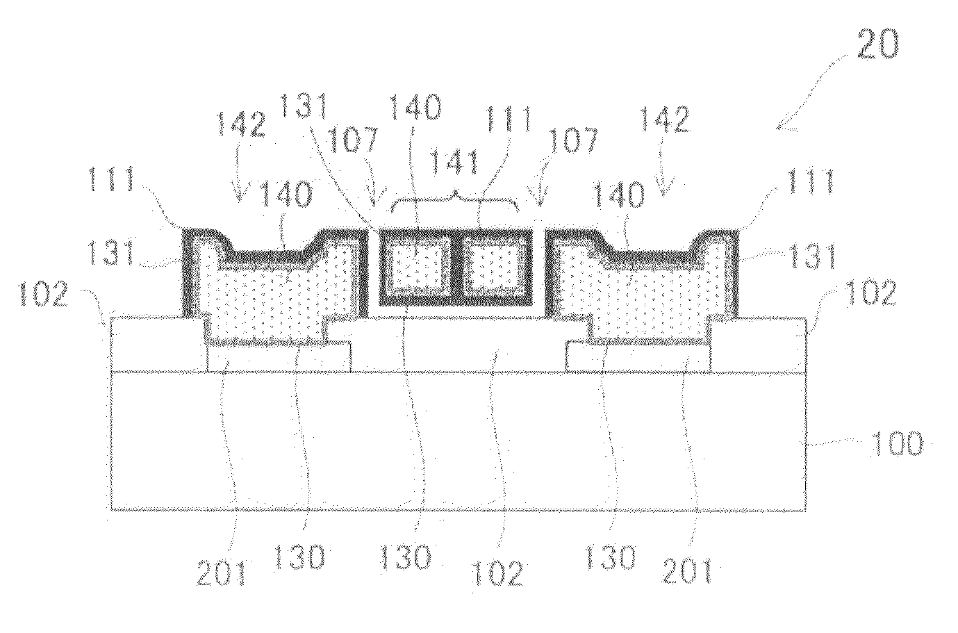
[0073]A second embodiment of the MEMS resonator according to the present invention will now be described with reference to the drawings. FIG. 7A is a top view showing a MEMS resonator 20 which is the second embodiment of the present invention. FIG. 7B is a cross-section showing the MEMS resonator 20 taken along 7B-7B line of FIG. 7A. Although a basic structure of the MEMS resonator 20 of the second embodiment is similar to that of the MEMS resonator 10 of the first embodiment, a movable electrode and fixed electrodes of the MEMS resonator 20 are different from the first embodiment. As described in the first embodiment, a movable electrode and fixed electrodes are usually formed from a conductive material such as poly-silicon and Poly-SiGe into which impurities are doped. This is because a single metal employed as the electrode material is not sufficiently hard and not excellent in thermal characteristics such as a thermal expansion coefficient. However, since the poly-silicon and Po...


PUM


Abstract

A micro electro-mechanical system, which can be stably formed so as to prevent sticking of a movable part and which has a narrow gap, and a method of manufacturing the same are provided. The micro electro-mechanical system includes at least one fixed electrode formed above a principal surface of a semiconductor substrate and at least one movable electrode formed on the principal surface. The at least one movable electrode includes the movable part separated from the principal surface and the at least one fixed electrode. The movable part is movable with respect to the principal surface and the at least one fixed electrode. The method of manufacturing the micro electromechanical system includes a sacrifical film formation step for forming a sacrifical film above the principal surface, an electrode layer formation step for forming an electrode layer above the principal surface so as to cover over the sacrifical film, an etching step for partially etching the electrode layer via a pattern so as to form the at least one electrode and the at least one fixed electrode, a sacrifical film removal step for removing the sacrifical film, and a conducting film formation step for forming a conducting film on surfaces of the at least one electrode and the at least one fixed electrode.

Description

BACKGROUND OF THE INVENTION[0001]1. Field of the Invention[0002]The present invention relates to a micro electro-mechanical system (MEMS) and a method of manufacturing the same.[0003]2. Description of the Related Art[0004]A Micro Electro-Mechanical System (MEMS) is a device in which electric circuits (control part) and mechanical macrostructures (movable part) are integrated on one substrate. The micro electro-mechanical system is manufactured by using various microfabrication technologies such as semiconductor manufacturing technology and laser processing technology. In various industrial fields such as information and communication, medical treatment, bio, and cars, the micro electro-mechanical system is a key device which is small, highly accurate, and excellent in power saving. A MEMS resonator utilizing the MEMS technology drives an oscillator formed by a silicon micro-fabrication technology and resonates the oscillator by utilizing an electrostatic force and electromagnetic fo...

Claims


Application Information

Patent Timeline
Patent Type & Authority Applications(United States)
IPC IPC(8): H01L23/48H01L21/02H01L21/44
CPCB81B2201/0271B81B2203/0118B81B2203/04B81C1/00944H03H2009/02496H01L28/40H03H3/0077H03H9/2457B81C2201/112
Inventor NAKAMURA, MAKIKO
Owner LAPIS SEMICON CO LTD
Why Eureka
Try Eureka