[0012][I] One aspect of the present invention is a focal position determining method for determining a focal position of an objective lens focused on an observed target region in a specimen. The focal position determining method according to one aspect of the present invention includes measuring any one of the focal position of the objective lens at a near point and the focal position of the objective lens at a far point or both so as to determine the focal position of the objective lens focused on the observed target region based on the measured focal position.
[0072]In the above-described (7), the present invention may select one focal position (specifically, the focal position (substantial focal position) at the near point of the objective lens or the focal position (substantial focal position) at the far point of the objective lens) from the plural focal positions accumulated by the execution based on the plural
feature data accumulated by the execution, and in the above-described (8), the present invention may determine the position apart from the selected focal position by a predetermined distance as the focal position of the objective lens that is focused on the observed target region in the specimen, based on the selected one focal position and the predetermined distance.
[0012][I] One aspect of the present invention is a focal position determining method for determining a focal position of an objective lens focused on an observed target region in a specimen. The focal position determining method according to one aspect of the present invention includes measuring any one of the focal position of the objective lens at a near point and the focal position of the objective lens at a far point or both so as to determine the focal position of the objective lens focused on the observed target region based on the measured focal position.
[0073]The present invention may further execute: (10) imaging the luminescent image of the specimen by using the
CCD camera at the focal position determined at (8); (11) calculating the
feature data based on the imaged image; (12) changing the focal position determined at (8); (13) imaging the luminescent image of the specimen by using the
CCD camera at the changed focal position; (14) calculating the
feature data based on the imaged image; (15) comparing the feature data calculated at (11) and the feature data calculated at (14); (16) when the feature data calculated at (14) is greater as a result of the comparison, determining again the focal position changed at (12) as the focal position of the objective lens focused on the observed target region in the specimen.
[0017]One aspect of the present invention is a feeble light detecting method in which an image of a test specimen of a biological origin is described, a desired area is extracted from the image, and the area is displayed or recorded as magnified.
[0074]In the present invention, an aperture may be arranged as decentered for example relative to the
optical axis at the
pupil position of an illumination optical
system including the
light source used at (1). Further, a
narrow band-pass filter may be arranged at the illumination optical
system including the
light source used at (1). The present invention may use a
light source emitting monochromatic visible light as the light source used in (1). The present invention may use a
living cell or tissue as the specimen.
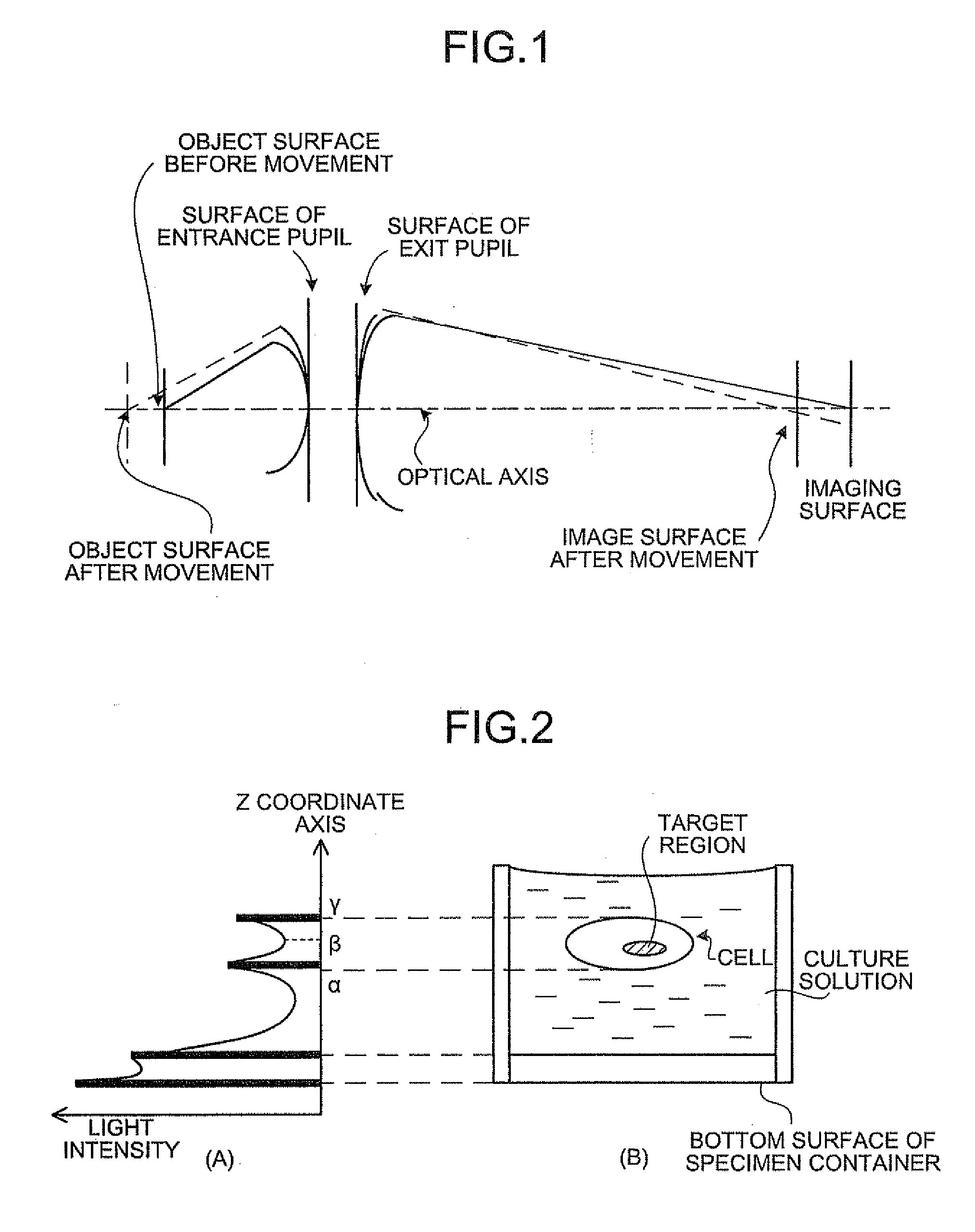
[0080]When a
magnification of the observation optical
system is reduced in a case where a
living cell is observed with a higher contrast, an angle of
diffraction light passing through the observation optical system is limited. Therefore, the contrast of the observation image can be increased.
[0074]In the present invention, an aperture may be arranged as decentered for example relative to the
optical axis at the
pupil position of an illumination optical system including the light source used at (1). Further, a
narrow band-pass filter may be arranged at the illumination optical system including the light source used at (1). The present invention may use a light source emitting monochromatic visible light as the light source used in (1). The present invention may use a
living cell or tissue as the specimen.
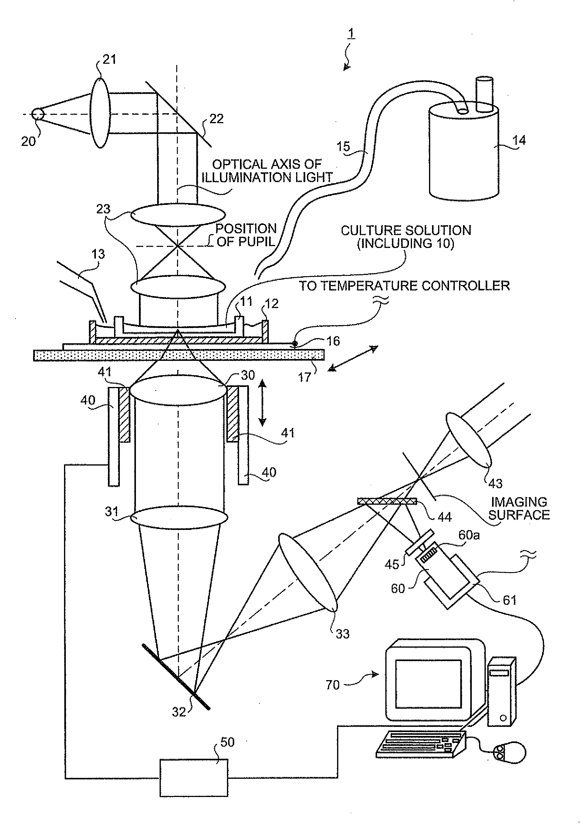
[0079]Specifically, by utilizing the phenomena described above, a clear image of a living
cell obtained by illumination light (illumination image) can be obtained, so that the observation same as that by a phase contrast
microscope or a differential interference
microscope can be carried out. As a result, the produced amount of the
phase difference achieves the function equal to the function of a phase film used in the phase contrast
observation method, whereby contrast proportional to the phase distribution of the living
cell can be provided to the observation image. Consequently, a living
cell that is colorless and transparent can be observed with a
high contrast.
[0074]In the present invention, an aperture may be arranged as decentered for example relative to the
optical axis at the
pupil position of an illumination optical system including the light source used at (1). Further, a
narrow band-pass filter may be arranged at the illumination optical system including the light source used at (1). The present invention may use a light source emitting monochromatic visible light as the light source used in (1). The present invention may use a living cell or tissue as the specimen.
[0013]Another aspect of the present invention is a focal position determining method for determining a focal position of an objective lens focused on an observed target region in a specimen. The focal position determining method according to one aspect of the present invention includes a light irradiating step of irradiating light to the specimen, a focal position changing step of changing the focal position of the objective lens, a focal position measuring step of measuring the focal position that is changed at the focal position changing step, a specimen imaging step of imaging the specimen to which light is irradiated at the light irradiating step, at the focal position changed at the focal position changing step, a feature data calculating step of calculating feature data characterizing the imaged
image based on the image taken at the specimen imaging step, an executing step of repeatedly executing the focal position changing step, focal position measuring step, specimen imaging step, and feature data calculating step, a focal position selecting step of selecting at least one focal position from the plural focal positions accumulated by the execution of the executing step based on the plural feature data accumulated by the execution, and a focal position determining step of determining the focal position of the objective lens focused on the observed target region based on the focal position selected at the focal position selecting step.
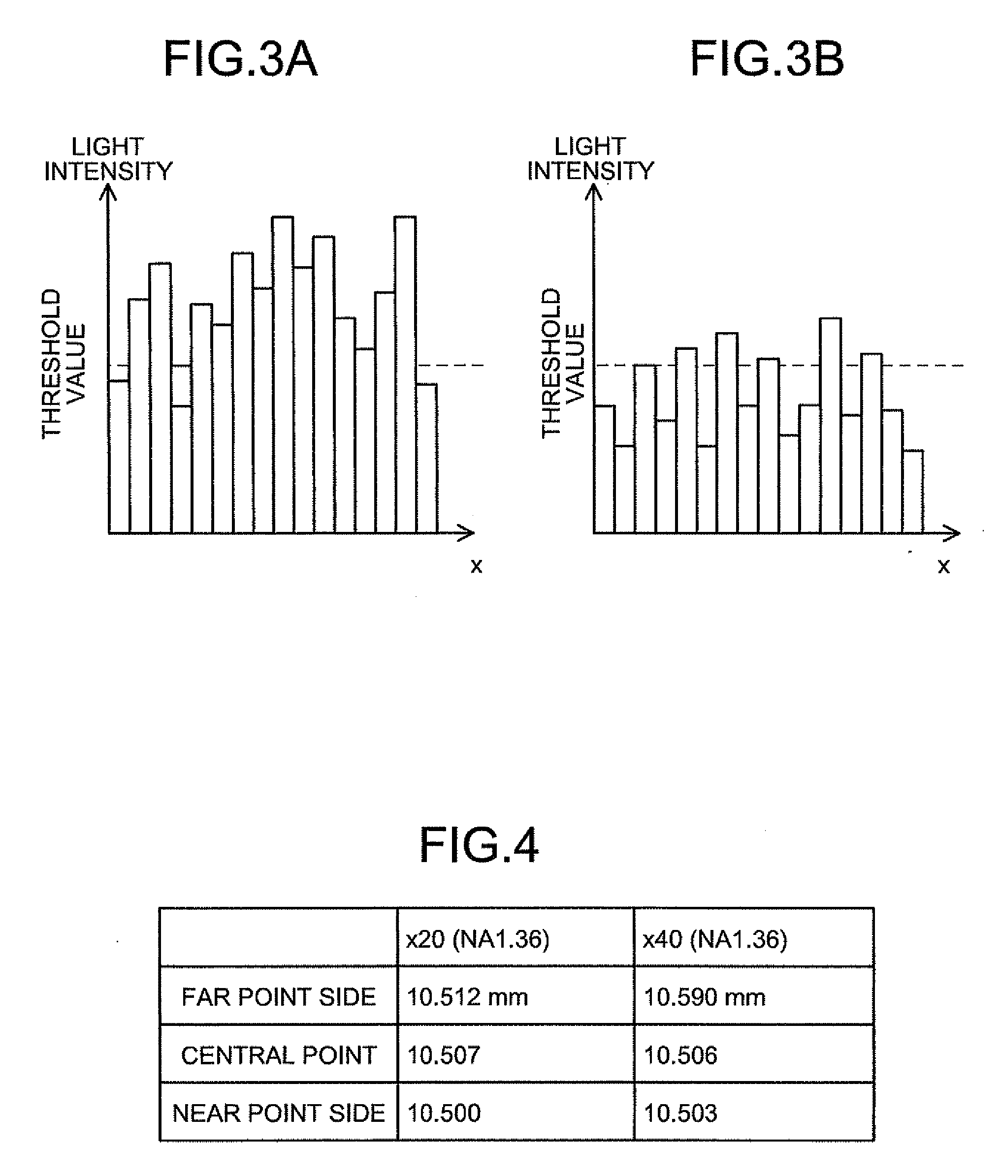
[0015]One aspect of the present invention is the focal position determining method for determining a focal position of an objective lens focused on an observed target region in a specimen, wherein the specimen is imaged while moving the objective lens, as well as the focal position of the objective lens is measured, a contrast that is the difference between the maximum value and the minimum value of a pixel value of each pixel composing the image is calculated based on the imaged image, and the focal position of the objective lens focused on the observed target region is determined based on the calculated contrast and the measured focal position of the objective lens.
[0015]One aspect of the present invention is the focal position determining method for determining a focal position of an objective lens focused on an observed target region in a specimen, wherein the specimen is imaged while moving the objective lens, as well as the focal position of the objective lens is measured, a contrast that is the difference between the maximum value and the minimum value of a pixel value of each pixel composing the image is calculated based on the imaged image, and the focal position of the objective lens focused on the observed target region is determined based on the calculated contrast and the measured focal position of the objective lens.
[0015]One aspect of the present invention is the focal position determining method for determining a focal position of an objective lens focused on an observed target region in a specimen, wherein the specimen is imaged while moving the objective lens, as well as the focal position of the objective lens is measured, a contrast that is the difference between the maximum value and the minimum value of a pixel value of each pixel composing the image is calculated based on the imaged image, and the focal position of the objective lens focused on the observed target region is determined based on the calculated contrast and the measured focal position of the objective lens.
[0003]The present invention relates to a focal position determining method and a focal position determining apparatus that determine a focal position of an objective lens focused on an observed target region in a specimen.
[0012][I] One aspect of the present invention is a focal position determining method for determining a focal position of an objective lens focused on an observed target region in a specimen. The focal position determining method according to one aspect of the present invention includes measuring any one of the focal position of the objective lens at a near point and the focal position of the objective lens at a far point or both so as to determine the focal position of the objective lens focused on the observed target region based on the measured focal position.
[0016][II] One aspect of the present invention is a feeble light detecting apparatus that describes an image of a test specimen of a biological origin by using optical imager. The feeble light detecting apparatus according to one aspect of the present invention includes an image forming step of describing the image of the test specimen with the use of the optical imager, an image extracting step of extracting a desired area from the image obtained at the image forming step, and an image magnifying step of magnifying the area obtained at the image extracting step.

