Solid electrolytic capacitor

a solid electrolyte and capacitor technology, applied in the direction of liquid electrolytic capacitors, fixed capacitors, fixed capacitor details, etc., can solve the problems of reducing the esr demand from the market, affecting the production efficiency of solid electrolyte, and deteriorating esr, so as to reduce esr, prevent increase in unnecessary resistance, and suppress the effect of film thickness of solid electrolyte layer in the cathode forming par

Active Publication Date: 2008-09-25
PANASONIC CORP
View PDF6 Cites 9 Cited by
  • Summary
  • Abstract
  • Description
  • Claims
  • Application Information

AI Technical Summary

Benefits of technology

[0028]According to the configuration, diffusion of the heat of quantity through the joint part at the time of laser welding can be reduced, and a stable welded state can be obtained because the quantity of heat is concentrated to the welding part; therefore an effect of achieving low ESR by improving the ESR can be obtained.
[0030]According to the configuration, since a portion of the anode electrode melted at the time of welding flows into the through hole to electrically connect the anode electrode parts of the elements with each other, an effect of reducing ESR by joining the entirety of a plurality of laminated elements can be obtained.
[0032]According to the configuration, even if sputter is scattered at the time of welding, since the insulating resin part is covered with a portion of the joint part, the sputter does not have any influence, so that highly reliable welding can be carried out stably, and the high reliability and the low ESR can be achieved.
[0034]According to the configuration, since the time for attaining a desired film thickness of a solid electrode layer is shortened at the time of forming the solid electrolyte layer by electropolymerization, a portion to be formed to a film thickness more than necessary can be reduced at the point where a portion in which the solid electrolyte layer is produced most slowly reaches to the desired film thickness, so that variation in film thickness of the solid electrolyte layer in the cathode forming part can be suppressed, and thus the effect of reducing ESR by preventing increase in unnecessary resistance can be obtained.
[0035]As heretofore described, according to the solid electrolytic capacitor of the present invention, by the configurations corresponding to each problem mentioned above, the effect of reducing ESR by joining the entirety of a plurality of laminated elements can be obtained.

Problems solved by technology

Therefore, as a first problem, there is a problem of difficulty in carrying out the welding work by providing an equal quantity of heat to all laminated elements 111 because of partial escape of the quantity of heat at the time of welding, to anode corn terminal 116 via connecting part 116b. Therefore, even though the welding strength is ensured, because of generation of irregularity in the welded state, the ESR was deteriorated due to the presence of a too-much-welded portion or a portion insufficiently welded.
Moreover, as a second problem, since the dielectric oxide coating film layer is formed on the surface of anode electrode part 114 of element 111, irregularity can easily be generated in the welding work.
Moreover, as a third problem, sputter may be generated at the time of welding by laser mentioned above, and the generated sputter is scattered in the periphery.
However, as a fourth problem, since the ESR value of element 121 main body is high, a problem occurs that a further lower ESR demanded from the market cannot be sufficiently achieved.
However, at the moment when point D has the desired film thickness, points B and A have a film thickness thicker than that of point D. Therefore, variation in the film thickness of the solid electrolyte layer is generated in cathode forming part 130, so that unnecessary resistance is increased at a portion formed to a film thickness more than necessary, and thus a problem of ESR deterioration occurs.

Method used


Image

  • Solid electrolytic capacitor
  • Solid electrolytic capacitor
  • Solid electrolytic capacitor

Examples


exemplary embodiment 1

[0066]Hereafter, a solid electrolytic capacitor according to a first exemplary embodiment of the present invention will be described with reference to the drawings.

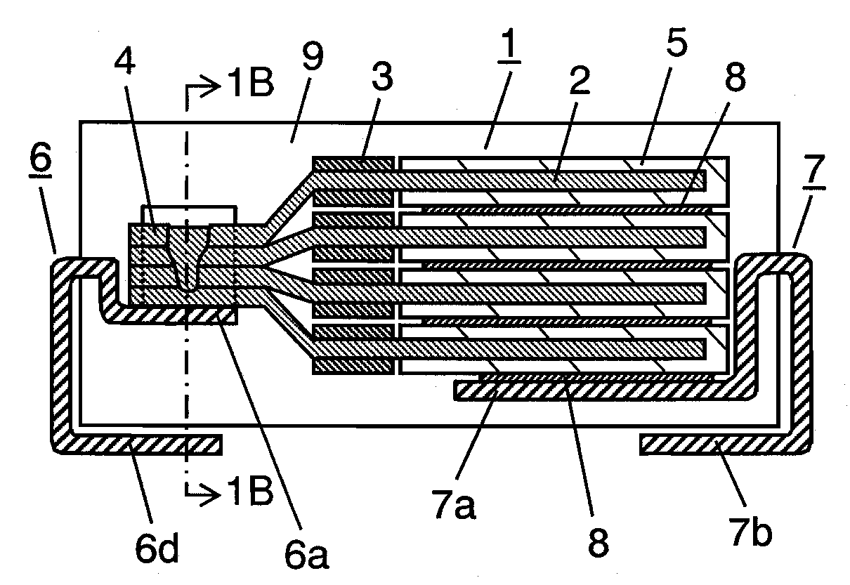
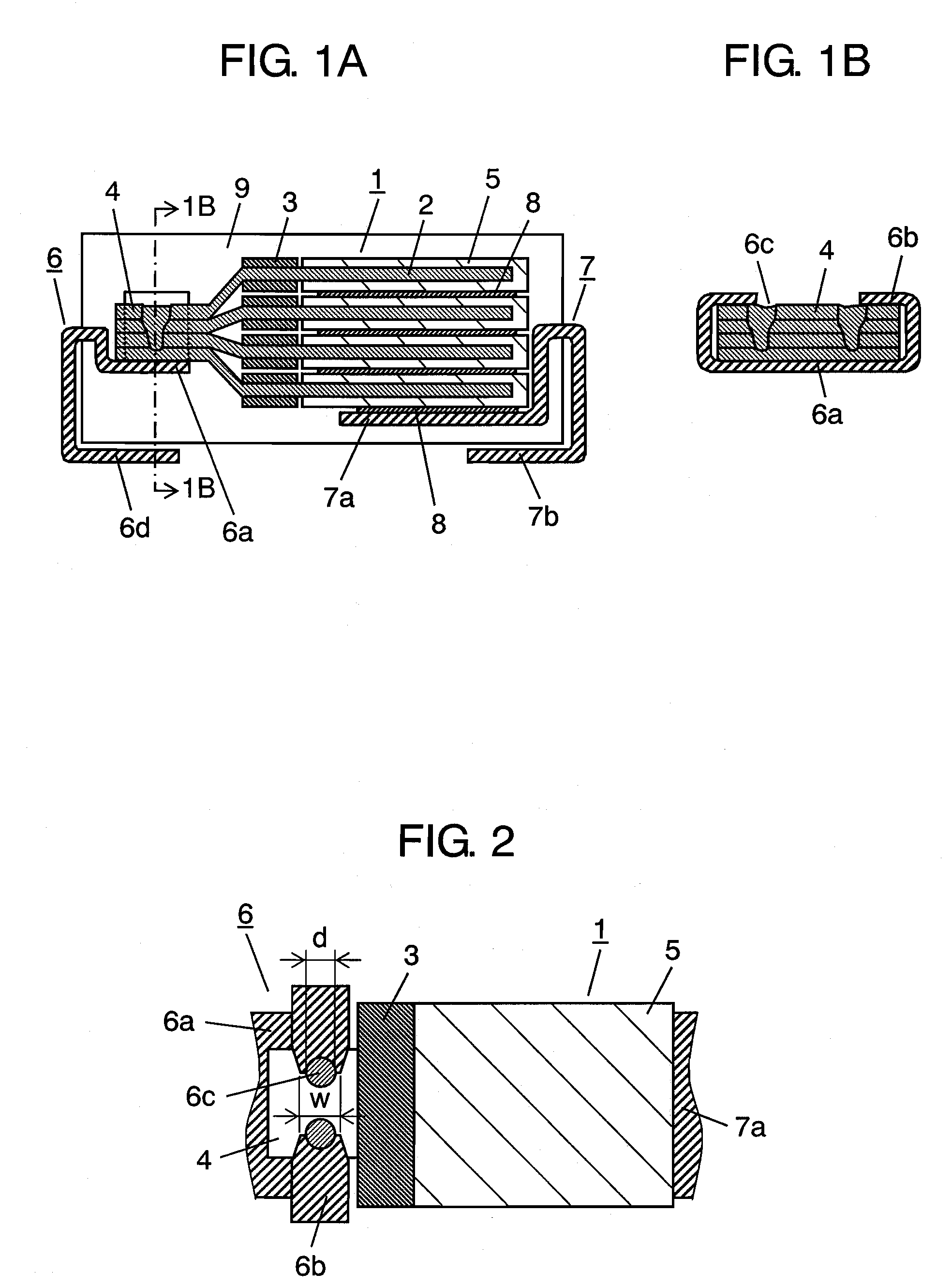
[0067]FIGS. 1A and 1B are a front cross-sectional view showing the configuration of a solid electrolytic capacitor in the first embodiment of the present invention and a side cross-sectional view taken along the 1B-1B line, FIG. 2 is a plan view of the solid electrolytic capacitor before external mounting, and FIG. 3 is a cross-sectional view showing the configuration of an element to be used for the solid electrolytic capacitor.

[0068]In FIGS. 1A to 3, element 1 is separated into anode electrode part 4 and a cathode forming part (not shown) by providing insulating resist part 3 made of an insulating resin such as a polyimide resin or a silicone resin after forming dielectric oxide coating film layer 2a by roughing the surface of anode member 2 made of an aluminum foil as a valve function metal (valve metal). Then, by succ...

exemplary embodiment 2

[0082]Hereinafter, a solid electrolytic capacitor according to a second exemplary embodiment of the present invention will be described with reference to the drawings.

[0083]The present embodiment has the configuration in which the anode com terminal of the solid electrolytic capacitor described with reference to FIGS. 1A to 2 in the first embodiment is partially changed. Since the other configuration is the same as that of the first embodiment, the same reference numerals are given to the same portions so as not to repeat detailed description thereof, and only different portions will be described hereinafter with reference to the drawings. Moreover, also in the following exemplary embodiments, the same reference numerals are given for the same contents as in the already-made description, and the description is omitted.

[0084]FIG. 5 is a plan view of the solid electrolytic capacitor according to the second embodiment of the present invention before external mounting. In FIG. 5, anode ...

exemplary embodiment 3

[0087]Hereinafter, a solid electrolytic capacitor according to a third exemplary embodiment of the present invention will be described with reference to the drawings.

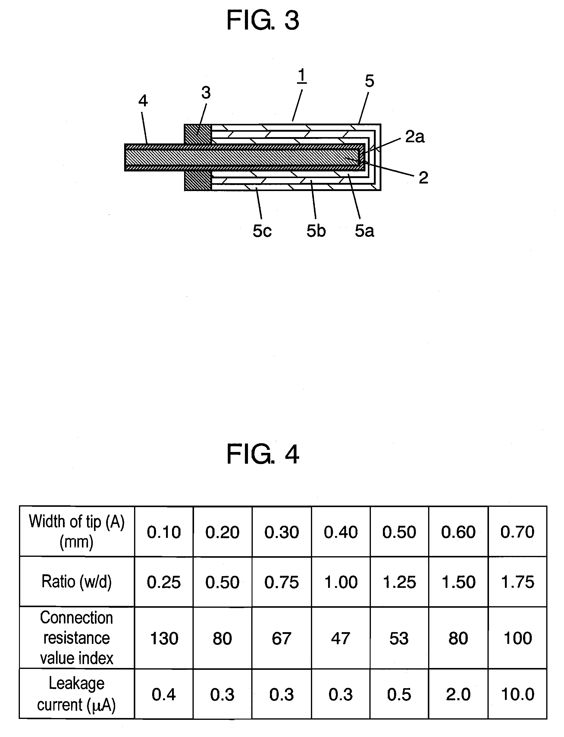
[0088]FIG. 6A is a front cross-sectional view showing the configuration of the solid electrolytic capacitor according to the third embodiment of the present invention, FIG. 6B is a side cross-sectional view taken along the line 6B-6B thereof, FIG. 7 is a plan view of the solid electrolytic capacitor before external mounting, and FIG. 8 is a cross-sectional view showing the configuration of an element to be used for the solid electrolytic capacitor.

[0089]In FIGS. 6A to 8, flat plate-like element 1 is separated into anode electrode part 4 and cathode forming part (not shown) by providing insulating resist part 3 after forming dielectric oxide coating film layer 2a by roughing the surface of anode member 2 made of an aluminum film as a valve function metal. By successively laminating and forming cathode layers including so...


PUM


Abstract

Cathode electrode part 5 of flat plate-like element 1 is joined with cathode com terminal 7 with a conductive adhesive or the like. Element mounting part 6a of anode terminal 6 is provided with a pair of joint parts 6b for wrapping anode electrode part 4 from both sides. The tips of joint parts 6b and anode electrode part 4 are joined by laser welding such that the ratio (w / d) of the width (w) of each tip of joint parts 6b and the diameter (d) of the welding trace to be welded is 0.5 to 1.5, and more preferably, 0.5 to 1.25 for providing low ESR means for concentrating the quantity of heat at the time of welding on welding parts 6c without escape. Therefore, a stable welded state is obtained, so that the ESR is improved for achieving low ESR of the solid capacitor.

Description

FIELD OF THE INVENTION[0001]The present invention relates in particular to a solid electrolytic capacitor with low impedance characteristics using a conductive polymer as a solid electrolyte out of capacitors to be used for various kinds of electronic devices.BACKGROUND OF THE INVENTION[0002]With the current tendency that electronic devices use higher frequencies, a capacitor having better impedance characteristics in a high frequency range than those of the conventional configuration is required also for a capacitor as one of the electronic parts. In order to meet such a demand, various solid electrolytic capacitors using a conductive polymer having high electric conductivity as the solid electrolyte have been discussed.[0003]Moreover, recently, a small size and a large capacity are strongly demanded for a solid electrolytic capacitor to be used around a CPU of a personal computer. Furthermore, corresponding to the tendency toward higher frequencies, lower ESR (equivalent series re...

Claims


Application Information

Patent Timeline
Patent Type & Authority Applications(United States)
IPC IPC(8): H01G4/06
CPCH01G9/012H01G9/15H01G9/14
Inventor OZAWA, MASATOISHIZAKI, KATSUHISAKAWAHITO, KAZUOOMORI, MINORUMARUHASHI, YOSHIRO
Owner PANASONIC CORP
Why Eureka
Try Eureka