Organic electroluminescent device

an electroluminescent device and organic technology, applied in the direction of luminescent compositions, luminescent screens, discharge tubes, etc., can solve the problems of not getting data concerning the improvement of durability and the inability to improve the durability effect of deuterium atoms

Inactive Publication Date: 2008-09-25
UDC IRELAND
View PDF7 Cites 76 Cited by
  • Summary
  • Abstract
  • Description
  • Claims
  • Application Information

AI Technical Summary

Benefits of technology

[0102]The emission maximum wavelength of the phosphorescent material (containing an iridium complex of the invention) contained in a light-emitting device of the invention is preferably from 350 nm to 500 nm, more preferably from 370 to 490 nm, still more preferably from 400 to 480 μm, and especially preferably from 420 to 470 nm.
[0103]A phosphorescent material containing an iridium complex of the invention is contained in a light-emitting layer in an amount of preferably from 0.1 to 40 mass % (weight %), more preferably from 0.5 to 20 mass %. When a phosphorescent material other than an iridium complex is used in combination with the iridium complex, the amount of the iridium complex is preferably 50 mass % or more, more preferably 80 mass % or more with respect to the total amount of phosphorescent materials.
[0104]When an iridium complex is used as a phosphorescent material, it is generally used in an amount of 1 to 50 mass parts (weight parts), more preferably 5 to 30 mass parts with respect to 100 mass parts of a host material.
[0105]As the host materials contained in a light-emitting layer of the invention, pyrrole host materials (including condensed rings of an aromatic hydrocarbon ring or a heterocyclic ring) and hydrocarbon host materials (preferably materials consisting of benzene rings alone) are preferred, pyrrole host materials are more ...

Problems solved by technology

Trials to introduce deuterium atoms to these iridium complexes are examined, but data concerning the improvement of durability are not obtained.
For example, the data of durability of devices in whi...

Method used


Image

  • Organic electroluminescent device
  • Organic electroluminescent device
  • Organic electroluminescent device

Examples


example 1

[0152]A device is manufactured and evaluated in the same manner as in Comparative Example 1 except for using compound (1-4) in place of compound A in Comparative Example 1. The emission of phosphorescence originating in compound (1-4) is observed.

example 2

[0153]A device is manufactured and evaluated in the same manner as in Comparative Example 1 except for using compound (2-4) in place of compound B in Comparative Example 2. The emission of phosphorescence originating in compound (2-4) is observed.

example 3

[0154]A device is manufactured and evaluated in the same manner as in Comparative Example 1 except for using compound (3-4) in place of compound C in Comparative Example 3. The emission of phosphorescence originating in compound (3-4) is observed.

[0155]A device is manufactured and evaluated in the same manner as in Example 1 except for using compound G in place of compound mCP (host material) in Example 1. The emission of phosphorescence originating in compound (1-4) is observed.

[0156]The results obtained are shown in relative values in Table 1 below.

TABLE 1Compound GHalfIncrease in driveExample No.Life of Luminance (relative value)voltage (ΔV)Comparative1.01.8 VExample 1Comparative2.2 (relative value to Comparative1.7 VExample 2Example 1)Comparative0.8 (relative value to Comparative2.1 VExample 3Example 1)Comparative1.0 (relative value to Comparative1.9 VExample 4Example 1)Comparative3.0 (relative value to Comparative1.6 VExample 5Example 1)Comparative3.1 (relative value to Compara...


PUM


Abstract

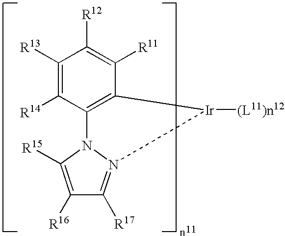
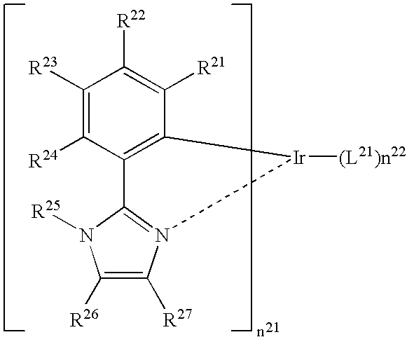
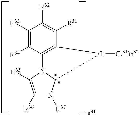
An organic electroluminescent device is provided and includes: a pair of electrodes; and at least one organic layer between the pair of electrodes, the at least one organic layer including a light-emitting layer. At least one of the at least one organic layers contains an iridium complex having a 5-membered heterocyclic structure consisting of a carbon atom and a nitrogen atom, and a deuterium atom on an SP2 carbon atom in the iridium complex.

Description

BACKGROUND OF THE INVENTION[0001]1. Field of the Invention[0002]The present invention relates to a light-emitting device, particularly an organic electroluminescent device (hereinafter also referred to as “light-emitting device” or “EL device”), capable of emitting light by converting electric energy into light.[0003]2. Background Art[0004]Organic electroluminescent devices are attracting public attention as promising display devices for capable of emitting light of high luminance with low voltage. An important characteristic of organic electroluminescent devices is consumed electric power. Consumed electric power is equal to the product of the voltage and the electric current, and the lower the value of voltage that is necessary to obtain desired brightness and the smaller the value of electric current, the lower is the consumed electric power of the device.[0005]As one attempt to lower the value of electric current that flows to a device, a light-emitting device utilizing luminesc...

Claims


Application Information

Patent Timeline
IPC IPC(8): H01J1/63
CPCC09K11/06C09K2211/1007C09K2211/1044H01L51/5016H01L51/0072H01L51/0081H01L51/0085C09K2211/185H10K85/6572H10K85/324H10K85/342H10K50/11H10K2101/10
Inventor IGARASHI, TATSUYAOKADA, HISASHI
Owner UDC IRELAND
Why Eureka
Try Eureka