[0007]According to the present invention, since the metal works are joined by the welding and the adhesive agent having the chain-reacting curing reaction function, the adhesive agent is cured by the energy from the welding properly, so that the joining of the metal works can be obtained rapidly and with energy-saving. Herein, the adhesive agent having the chain-reacting curing reaction function is, as disclosed in U.S. Pat. No. 6,599,954, for example, a resin composition that primarily comprises a photopolymerizable resin, a photo- and thermopolymerization initiator, and a photopolymerization initiator. Herein, when this adhesive agent is exposed to energy
radiation, such as
ultraviolet radiation,
electron beam, X-rays,
infrared radiation,
sunlight, visible light, laser beam (e g.,
excimer laser, CO2 laser), radiated heat rays, and other energy such as heat, a cation and a (first) heat of curing reaction are positively generated within the resin composition of the adhesive agent, and the curing reaction is further effected, like a
chain reaction, by the action of the cation and the (first) heat of curing reaction to successively generate an additional cation and an additional (second) heat of curing reaction, so that the resin composition of the adhesive agent is cured by means of the (first and second) reaction heat energies and the cation. By using this adhesive agent having the chain-reacting curing reaction function, the thickness of the metal works to be joined can be reduced as much as possible, and a weight reduction and a cost reduction of products can be attained. That is, the joining portions can be made properly continuous by applying the adhesive agent having the chain-reacting curing reaction function, so that the rigidity of the joining portions can be improved. This rigidity improvement can cause the above-described thinner thickness of the metal works and thereby the reductions of weight and costs Further, a secular deterioration of a joining portion with the adhesive agent can be properly restrained by the welding portion. Meanwhile, a joining area can be properly enlarged by the adhesive agent having the chain-reacting curing reaction function. Thus, the both can cover respective deficiencies, thereby providing a properly firm joining structure. The metal works to be joined eventually may comprise two members, three members or more.
[0008]According to an embodiment of the present invention, the gap is formed by an originally-provided uneven shape of the metal work. Thereby, the originally-provided uneven shape of the metal work is utilized as the gap for application of the adhesive agent having the chain-reacting curing reaction function, without making any gap for the adhesive agent particularly. Accordingly, the firm joining structure can be obtained easily The metal work with the originally-provided uneven shape may be made by injection molding,
casting, pressing or the like.
[0010]According to the above-described aspect of the present invention, by forming the joining face in the uneven shape, the metal works contact one another partially so as to provide the gap between the metal works. The adhesive agent having the chain-reacting curing reaction function within the gap is disposed previously, and the metal works are placed so as to contact one another. Then, the laser beam is radiated and thereby the welding portion, where the metal works contact one another substantially directly, are joined together with the laser welding. Meanwhile, the adhesive agent having the chain-reacting curing reaction function provided in the gap is cured by the
heat energy generated by the energy from the laser beam radiated in the
chain reaction manner, or the combination of this
heat energy generated in the
chain reaction manner and the energy itself of the laser beam, which is as described above in the present invention. As a result, even if the laser welding is used in which the radiation of the leaser beam is partial, the properly continuous joining portion can be provided by using the cured adhesive agent. Thus, it may not necessary to use a large-scaled forming device or
drying device, so that manufacturing costs can be reduced properly. Further, since the welding portion where the metal works contact one another substantially directly is provided adjacently to the gap provided by forming the joining faces of the metal works in the uneven shape, the joining area of the welding portion can be made small so as to increase contacting pressure properly at this portion, so that the metal works can be placed properly so as to contact one another with little gap therebetween at this welding portion. As a result, the proper and accurate laser welding can be obtained by preventing poor welding. Any kind of metal works or metal-
alloy works may be used as long as the laser welding can be applied to them. The welding portion where the metal works contact one another substantially directly may be configured so that there occurs a considerably small gap between the metal works compared to the gap that accommodates the adhesive agent having the chain-reacting curing reaction function.
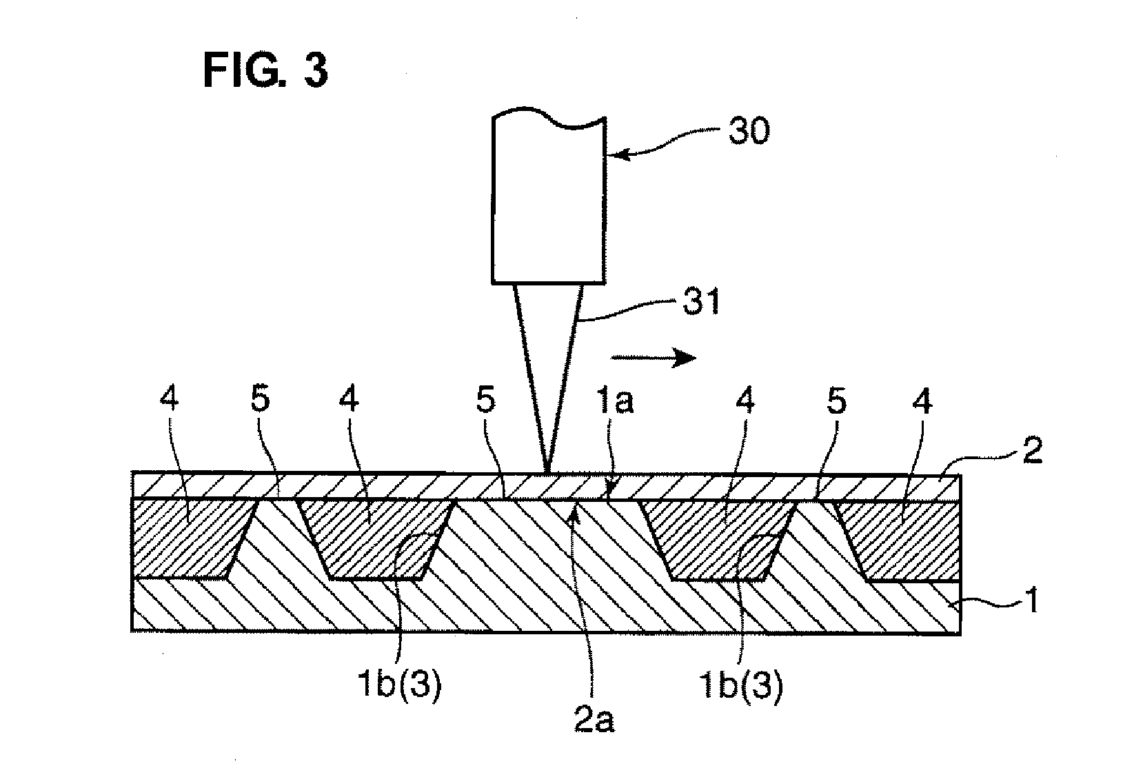
[0011]According to an embodiment of the above-described aspect of the present invention, the gap that accommodates the adhesive agent having the chain-reacting curing reaction function is provided by forming at least one of joining faces of the metal works in a recess shape Thereby, the disposition of the adhesive agent can be facilitated. Particularly, in a case where the adhesive agent is coated or injected, the adhesive agent remains in the recess properly, so that the application of the adhesive agent can be facilitated.
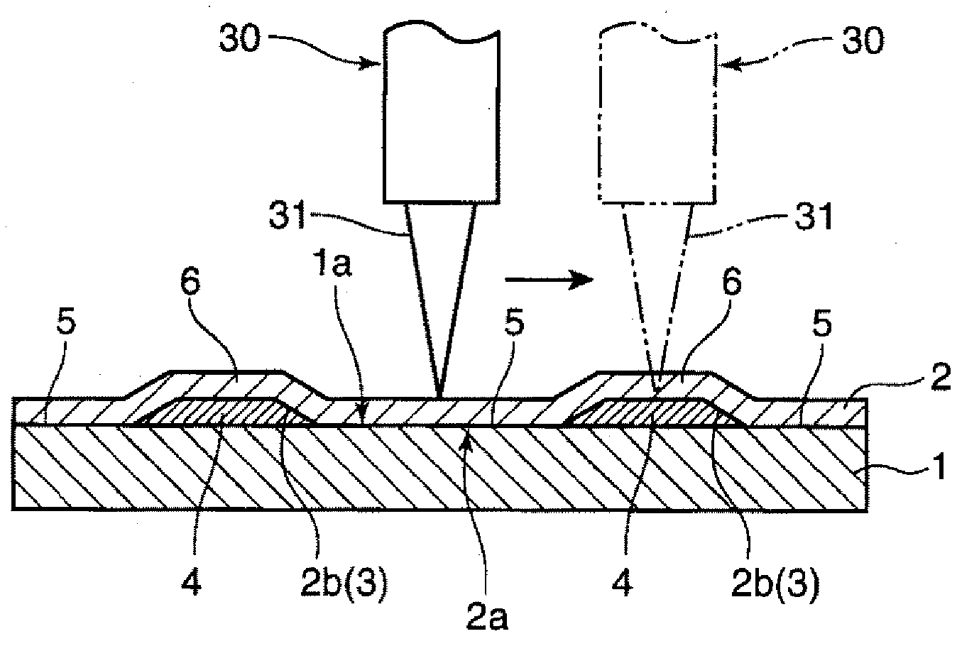
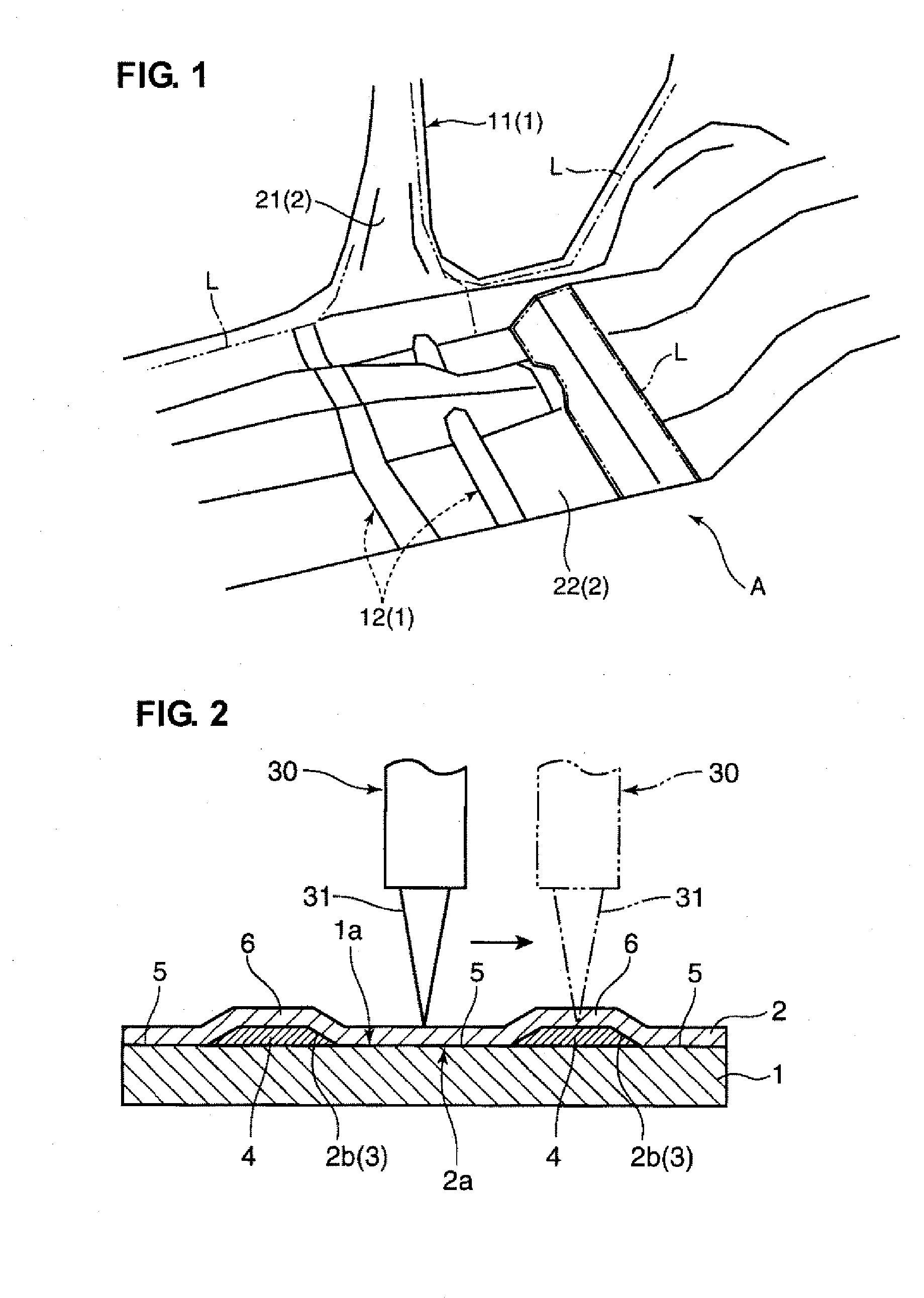
[0012]According to another embodiment of the above-described aspect of the present invention, at least one of the metal works has a projecting portion for accommodating the adhesive agent therein that is formed so as to project outward from the welding portion thereof, and the laser beam radiation device is located on a projection side of the projecting portion of the metal work and controlled so as to radiate the laser beam at the projecting portion accommodating the adhesive agent, focusing on the welding portion. Thereby, the welding portion where the metal works contact one another substantially directly can be properly welded with the laser beam, while the projecting portion with the adhesive agent is exposed to the laser beam that has a weaker energy than the laser beam applied to the welding portion. Thus, both the laser welding and the curing of the adhesive agent having the chain-reacting curing reaction function can be attained substantially at the same time.

