
Emboli protection devices and related methods of use

a protection device and shield technology, applied in the field of shield devices, can solve the problems of blockages, whether partial or full, that can have serious medical consequences, damage to the heart, and other vessels are also prone to narrowing

Inactive Publication Date: 2008-10-02
RESSEMANN THOMAS V +5
View PDF2 Cites 12 Cited by
  • Summary
  • Abstract
  • Description
  • Claims
  • Application Information

AI Technical Summary

Benefits of technology

"The invention provides methods and apparatus for reducing or removing blockages in blood vessels without causing embolization of particulate matter. The methods involve positioning an evacuation sheath assembly in the blood vessel and stopping normal antegrade blood flow for a short time while using a device to treat the blockage. The evacuation sheath assembly includes a tube with two lumens and sealing surfaces to create a seal with the blood vessel. The methods and apparatus can be used in procedures such as angioplasty or stent placement. The invention also provides an evacuation sheath assembly that can be expanded from a compressed configuration to an expanded configuration to capture embolic debris dislodged during the procedure. Overall, the invention provides safer and more effective methods for treating blockages in blood vessels."

Problems solved by technology

Such blockages, whether partial or full, can have serious medical consequences, depending upon their location within a patient's vascular system.
Narrowing or blockage of the coronary vessels that supply blood to the heart, a condition known as atherosclerosis, may cause damage to the heart.
Other vessels are also prone to narrowing, including carotids, renals, cerebrals, and other peripheral arteries.
The saphenous vein graft (SVG), however, is also susceptible to becoming occluded in a manner similar to that of the bypassed vessel.
Each of the above described procedures carries with it the risk that some of the treated plaque will be disrupted, resulting in embolic particulates released in the bloodstream.
These emboli, if allowed to flow through the vascular system, may cause subsequent infarctions or ischemia in the patient.
SVGs treated by angioplasty or atherectomy carry a particularly high risk of this result, but such problems are also encountered in the other types of procedures mentioned, such as carotids, or native coronary arteries, particularly those whose lesions include thrombus.
While this system has shown a decrease in emboli related complications in patients undergoing such treatments, the event rate remains significant.
One particular problem with this system is passing the guidewire and balloon through the narrowed or occluded area prior to occlusion with the balloon, creating the risk that emboli will be produced as the balloon passes through the blockage.
Thus, any particulate or plaque disturbed during this passage which forms emboli prior to inflation of the balloon is free to flow through the vascular system, increasing the risk for infarction or ischemia.
Also, any debris or particulate matter which gathers around the edges of the balloon may slip downstream during deflation and retrieval of the balloon.
In addition, this system requires that blood flow be totally occluded in the vessel for relatively prolonged intervals that may induce adverse cardiac events.
Although this may not be a problem clinically, many patients perceive the occlusion of blood flow for this period of time as problematic.
However, because the filter must pass through the blockage, it suffers from the same drawback as the previous system—risk of the creation of emboli during passage of the filter through the blockage.
In addition, it is difficult to deploy the filter securely against the walls of the vessel to prevent flow around the filter and any debris or particulate matter which gathers around the edges of the filter may slip downstream during its retrieval.
The filter also cannot prevent the passage of certain neurohumoral or vasoactive substances which are released into the blood during the procedure and may contribute to generalized vasospasm of the distal coronary tree.

Method used


Image

  • Emboli protection devices and related methods of use
  • Emboli protection devices and related methods of use
  • Emboli protection devices and related methods of use

Examples


Embodiment Construction

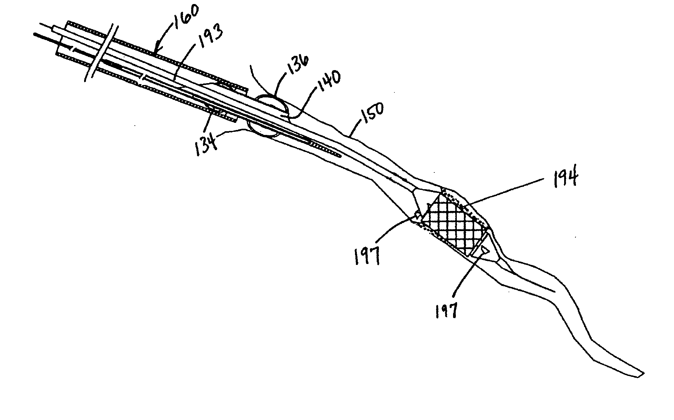
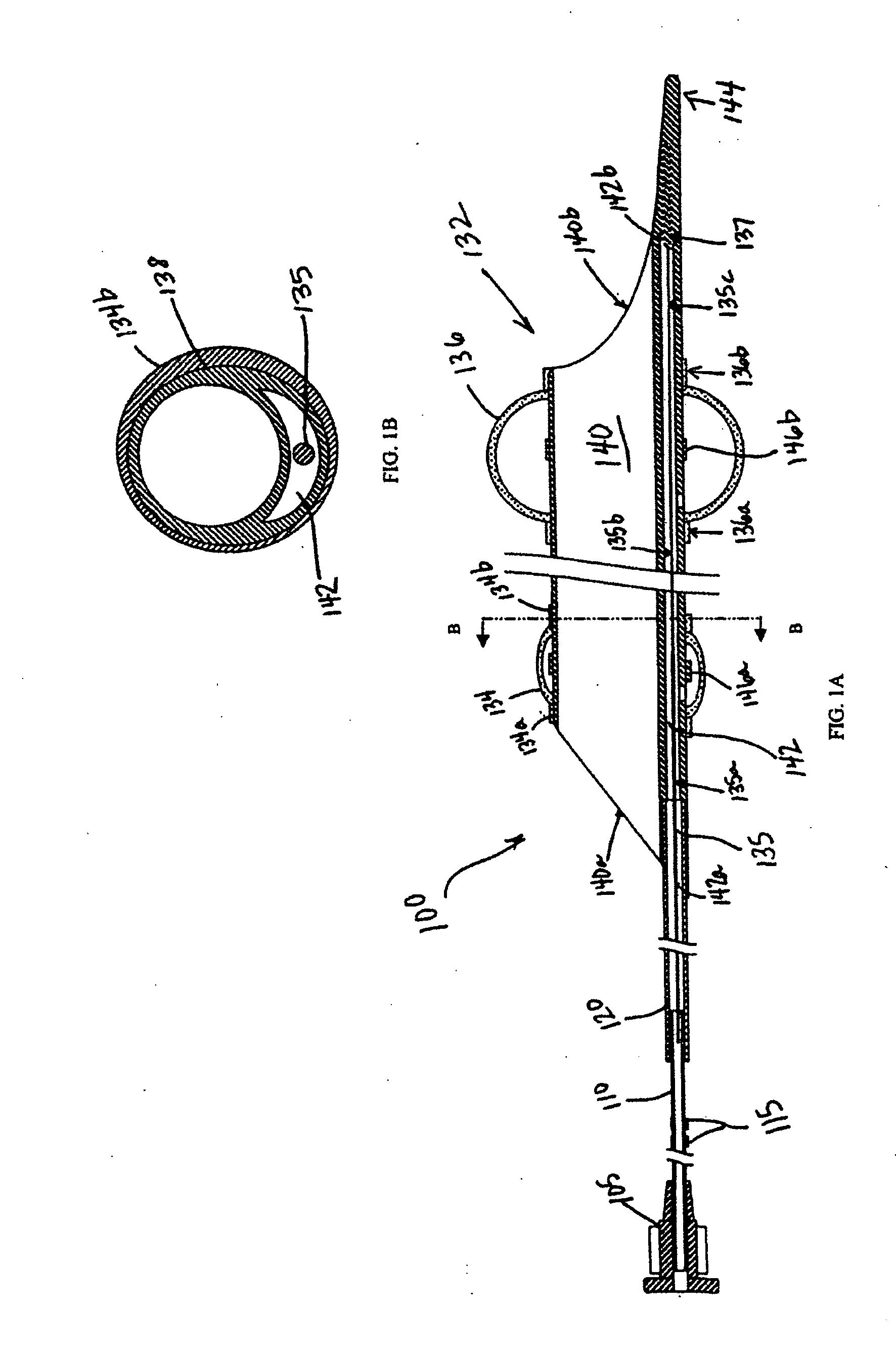
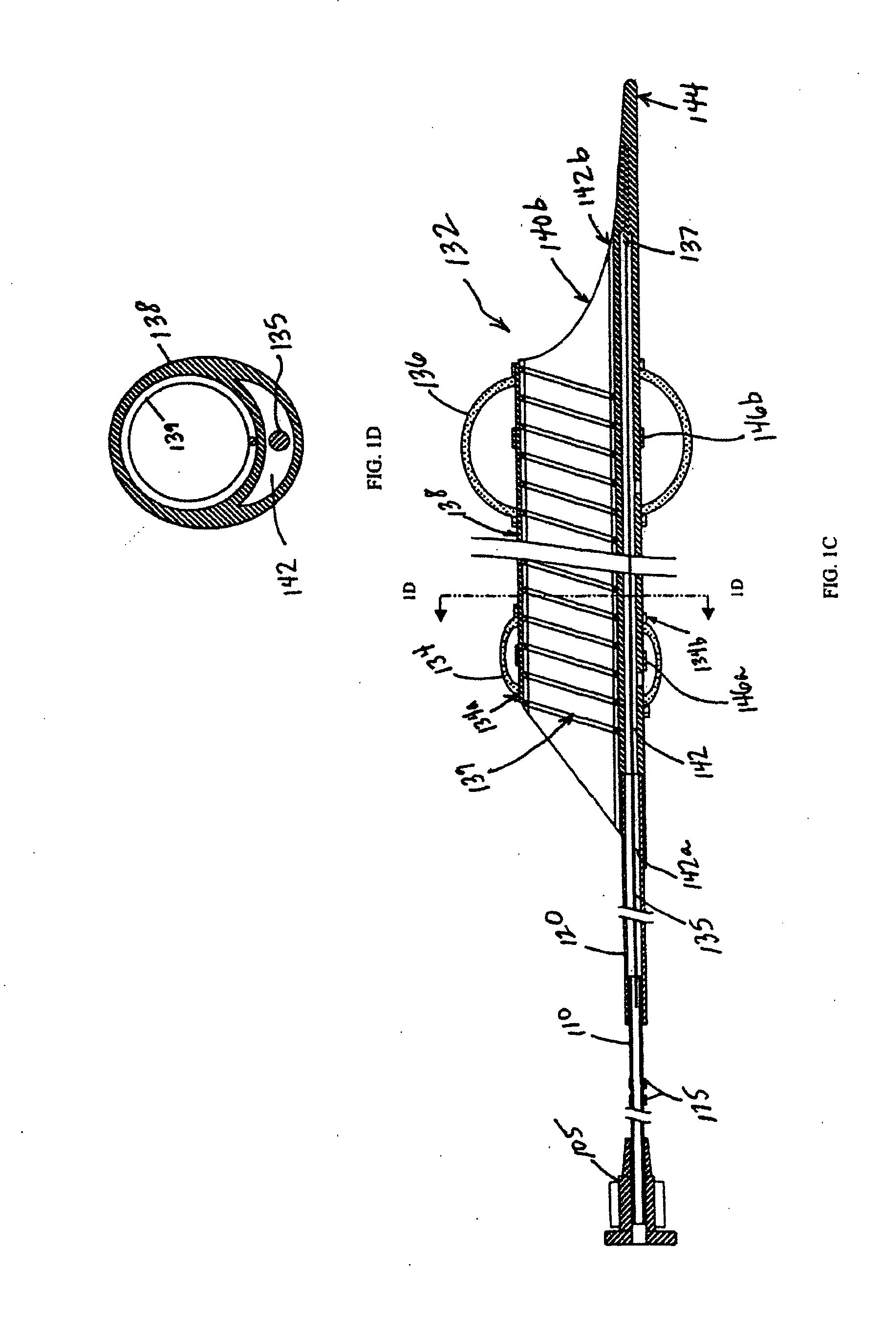
[0100]Reference will now be made in detail to the present embodiments of the invention, examples of which are illustrated in the accompanying drawings. Wherever possible, the same reference numbers will be used throughout the drawings to refer to the same or like parts.

[0101]The present invention provides a system and method for evacuating emboli, particulate matter, and other debris from a blood vessel, and particularly from an occluded blood vessel. As used herein, an “occlusion,”“blockage,” or “stenosis” refers to both complete and partial blockages of the vessels, stenoses, emboli, thrombi, plaque, debris and any other particulate matter which at least partially occludes the lumen of the blood vessel.

[0102]Additionally, as used herein, “proximal” refers to the portion of the apparatus closest to the end which remains outside the patient's body, and “distal” refers to the portion closest to the end inserted into the patient's body.

[0103]This method and apparatus are particularly ...


PUM


Abstract

An embolic protection system for treating a lesion in a blood vessel is provided. The embolic protection system includes a guide catheter, an evacuation sheath, a guidewire, and an infusion catheter. The guide catheter has a guidewire lumen. The evacuation sheath has an evacuation lumen and a sealing surface and is configured to move within the lumen of the guide catheter. The guidewire is configured to move within the lumen of the guide catheter and the evacuation lumen. The infusion catheter has an infusion lumen, at least one infusion port, and a guidewire lumen configured to accept the guidewire, the infusion catheter guidewire lumen being shorter than the guide catheter guidewire lumen. Furthermore, the infusion catheter is configured to move within the lumen of the guide catheter and the evacuation lumen over the guidewire. The system may further comprise a dilation catheter having a dilation balloon and a guidewire lumen.

Description

REFERENCE TO RELATED APPLICATIONS[0001]This is a divisional of U.S. patent application Ser. No. 09 / 940,986, filed on Aug. 29, 2001. This is also related to U.S. patent application Ser. No. 09 / 845,162, filed on May 1, 2001, and U.S. patent application Ser. No. 10 / 214,712, filed on Aug. 9, 2002. The entire contents of each of the above-referenced applications are expressly incorporated herein by reference in their entirety.FIELD OF THE INVENTION[0002]The present invention relates to apparatus and methods used to prevent the introduction of emboli into the bloodstream during and after surgery performed to reduce or remove blockage in blood vessels.BACKGROUND OF THE INVENTION[0003]Narrowing or occlusion of blood vessels, such as the walls of an artery, inhibit normal blood flow. Such blockages, whether partial or full, can have serious medical consequences, depending upon their location within a patient's vascular system. Narrowing or blockage of the coronary vessels that supply blood t...

Claims


Application Information

Patent Timeline
Patent Type & Authority Applications(United States)
IPC IPC(8): A61M29/00A61B17/12A61B17/00A61B17/22A61B19/00A61F2/06A61F2/82A61F2/84A61M25/00
CPCA61B17/12045A61B17/12109A61B17/12136A61B19/54A61B2017/12127A61B2017/22067A61F2/95A61B17/22A61B2017/22079A61B2017/22082A61B2017/22084A61B2217/005A61B2217/007A61B90/39
Inventor RESSEMANN, THOMAS V.HACKETT, STEVEN S.DUSBABEK, ANDREW J.OLSON, SCOTT A.KEITH, PETER T.WAHR, DENNIS W.
Owner RESSEMANN THOMAS V
Learn More