Combustor of a gas turbine engine

a gas turbine engine and combustor technology, applied in the direction of machines/engines, efficient propulsion technologies, light and heating apparatus, etc., to achieve the effect of simplifying the structure of the entire combustor, simplifying the structure of the combustor, and reducing the amount of fuel supply

Active Publication Date: 2008-10-09
KAWASAKI HEAVY IND LTD
View PDF7 Cites 25 Cited by
  • Summary
  • Abstract
  • Description
  • Claims
  • Application Information

AI Technical Summary

Benefits of technology

[0010]It is an object of the present invention to provide a combustor of a gas turbine engine based on the composite combustion system composed of the combination of the two combustion systems, i.e., the diffusion combustion system and the lean pre-mixture combustion system, which can provide secure fuel flow control with a simpler structure and a lower cost.
[0021]With the combustor of the gas turbine engine according to the present invention, the amounts of the fuel to be distributed to the pilot fuel passage and to the main fuel passage can be automatically controlled in accordance with the pressure of the fuel, only by providing the fuel distributor at the branch point where the assembled fuel passage is connected to both of the pilot fuel passage and the main fuel passage. Accordingly, there should be no need for providing flow rate control valves to the pilot fuel passage and to the main fuel passage, respectively. Therefore, the structure can be simplified and necessity of using a complicated control circuit can be eliminated, thereby reducing the cost of the combustor.

Problems solved by technology

This has been a substantial obstacle to the application of the composite combustion system requiring such an additional fuel control system (i.e., the flow control valves and controller) to the gas turbine engines for the small-size airplanes.

Method used


Image

  • Combustor of a gas turbine engine
  • Combustor of a gas turbine engine
  • Combustor of a gas turbine engine

Examples


Embodiment Construction

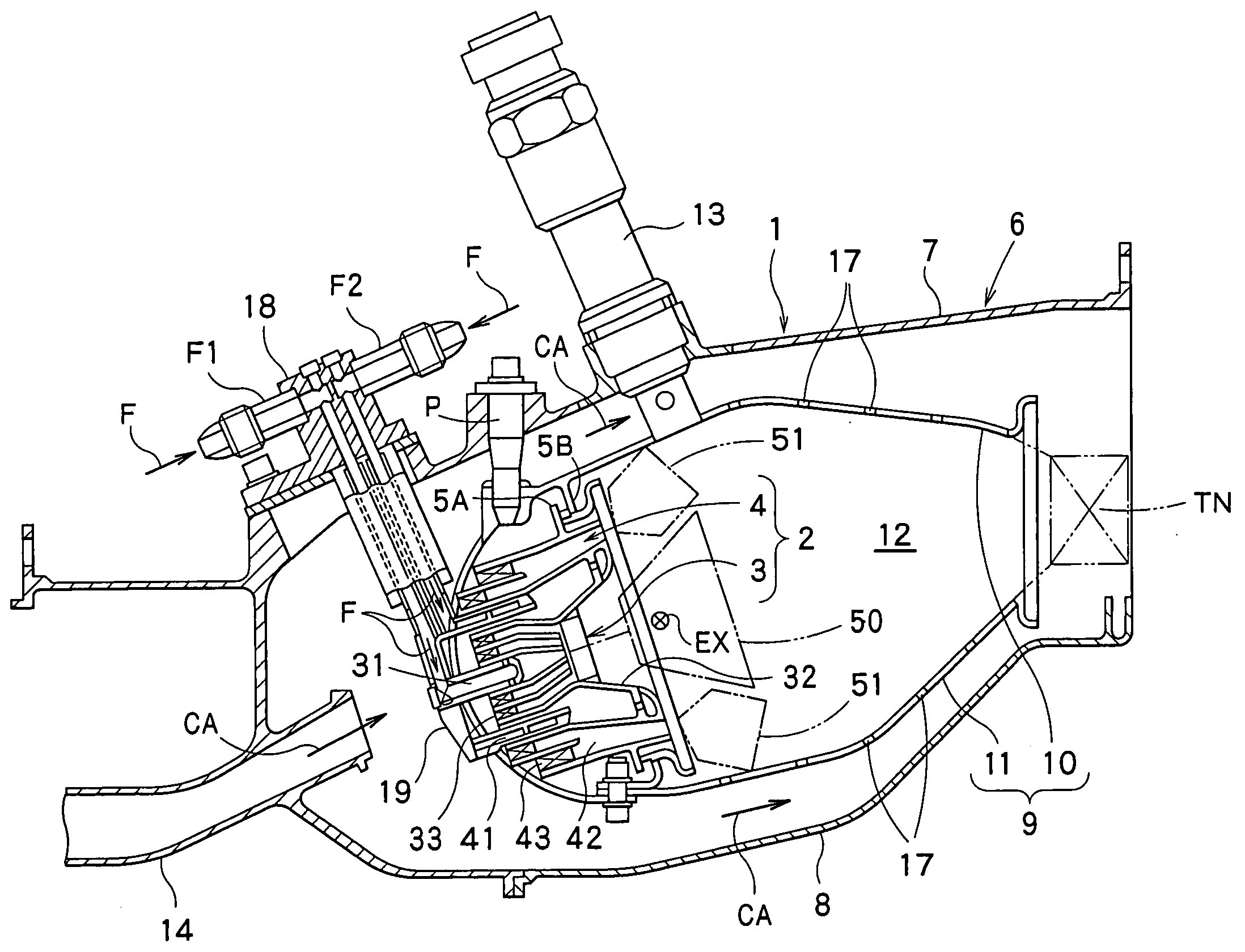
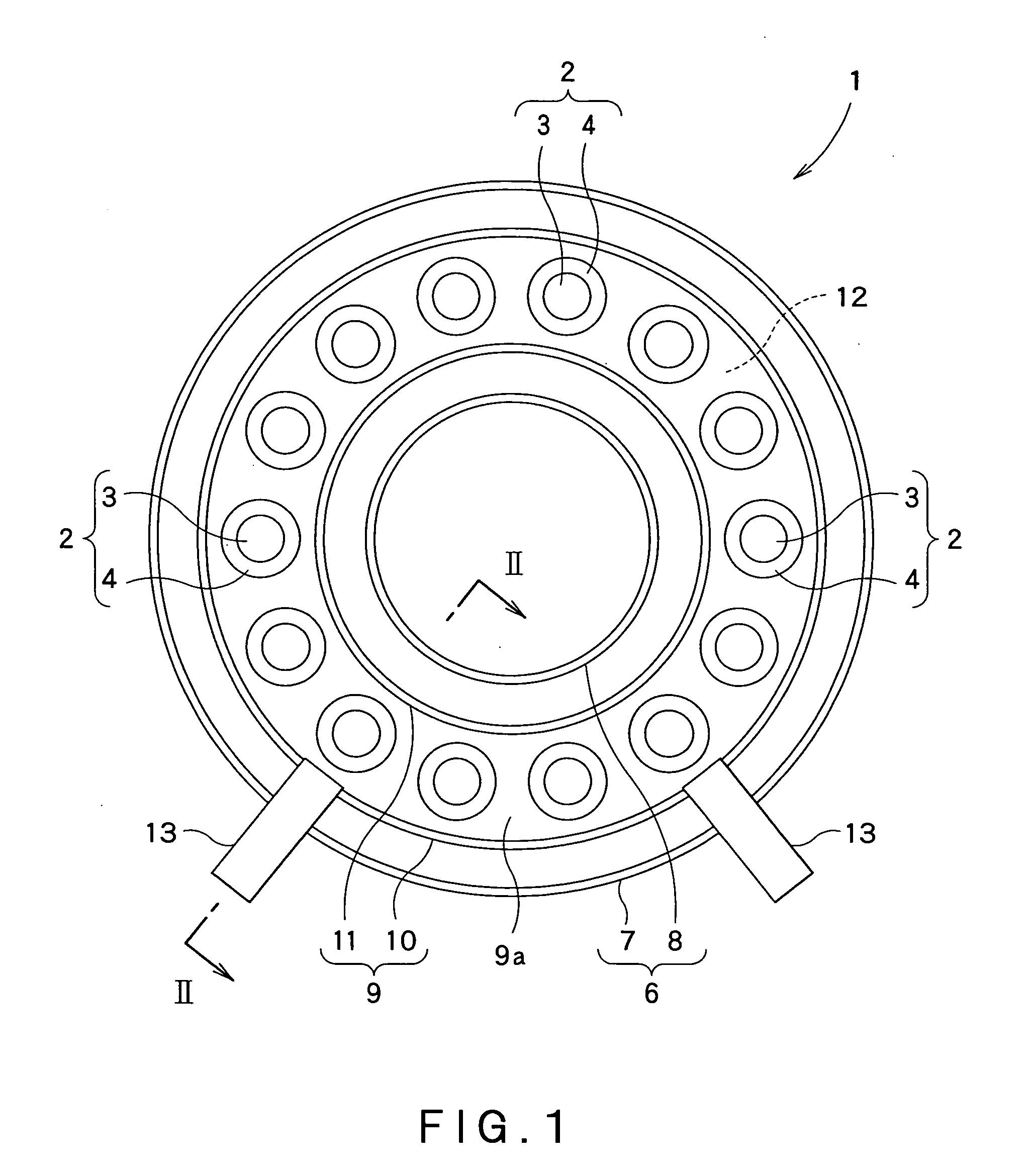
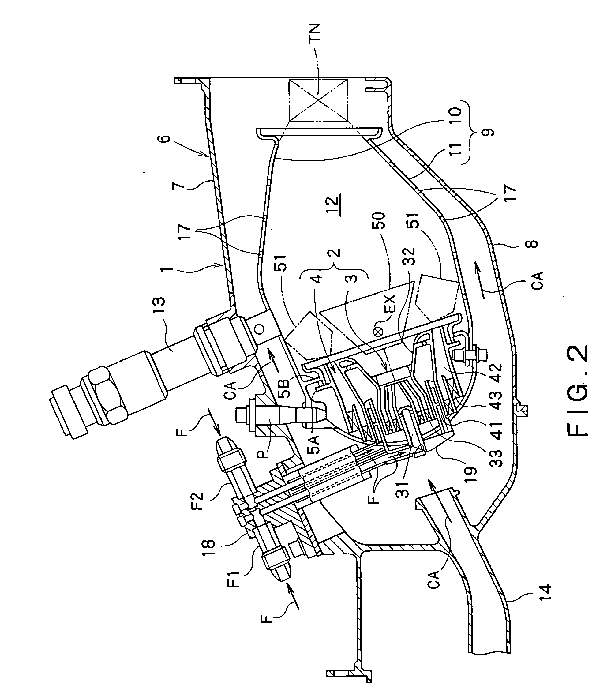
[0033]Hereinafter, preferred embodiments of the present invention will be described with reference to the drawings. FIG. 1 shows a head of a combustor 1 constituting a gas turbine engine according to a first embodiment of the present invention. The combustor 1 is configured to drive a turbine, by combusting a mixed gas or mixture to be formed by mixing a fuel with compressed air supplied from a compressor (not shown) of the gas turbine engine, and then supplying the so-formed high-temperature and high-pressure combustion gas created by such combustion to the turbine.

[0034]The combustor 1 is of an annular type, in which a combustor housing 6 having an annular internal space is constructed by arranging an annular inner casing 8 concentrically in an annular outer casing 7. In the annular internal space of the combustor housing 6, a combustion cylinder 9, which is constructed by arranging an annular inner liner 11 concentrically in an annular outer liner 10, is arranged concentrically w...


PUM


Abstract

The present combustor of gas turbine engine includes: a fuel injection unit including a fuel spray part to spray a fuel so that a diffusion combustion region is formed in a combustion chamber, and a pre-mixture supply part to supply a pre-mixture of a fuel and an air so that a pre-mixture combustion region is formed in the combustion chamber; and a fuel supply unit to supply the fuel to the fuel spray part and pre-mixture supply part. The fuel supply unit includes: a pilot fuel passage and a main fuel passage to supply the fuel to the fuel spray part and the pre-mixture supply part, respectively; an assembled fuel passage to supply the fuel to the pilot and main fuel passages; and a fuel distributor disposed at a branch point where the assembled fuel passage is connected to both the pilot and main fuel passages. The fuel distributor is configured to automatically control amounts of the fuel to be distributed to the pilot fuel passage and to the main fuel passage in accordance with the fuel pressure.

Description

CROSS REFERENCE TO RELATED APPLICATIONS[0001]This application is based upon the prior Japanese Patent Application No. 2007-99589 filed on Apr. 5, 2007, the entire contents of which are incorporated herein by reference.BACKGROUND OF THE INVENTION[0002]1. Field of the Invention[0003]The present invention relates to a combustor of a gas turbine engine including a fuel injection structure of a composite combustion type comprising a combination of two combustion systems, i.e., a diffusion combustion system and a lean pre-mixture combustion system.[0004]2. Description of the Related Art[0005]For the gas turbine engine, in view of the environmental protection, strict criteria are provided, with respect to the composition of exhaust gases to be generated by combustion. In the criteria, reduction of harmful matters, such as nitrogen oxides (hereinafter, referred to as NOx), is greatly required. On the other hand, in the case of large-size gas turbines and / or engines for airplanes, from the r...

Claims


Application Information

Patent Timeline
Patent Type & Authority Applications(United States)
IPC IPC(8): F02C7/00
CPCF02C7/228F23D2900/00015F23K5/06F23K2301/206F23K2401/201F23R3/286F23R3/343Y02T50/672F23K2300/206F23K2400/201Y02T50/60
Inventor ODA, TAKEOOGATA, HIDEKI
Owner KAWASAKI HEAVY IND LTD
Why Eureka
Try Eureka