Plasmon assisted control of optofluidics

a technology of optofluidics and lasers, applied in the direction of positive displacement liquid engines, glassware laboratories, water supply installations, etc., can solve the problems of not being desirable or possible to have nanoparticles freely suspended in liquid solution, and the utility of electrorowetting devices. great, droplet-based devices,

Active Publication Date: 2008-10-09
CALIFORNIA INST OF TECH
View PDF7 Cites 19 Cited by
  • Summary
  • Abstract
  • Description
  • Claims
  • Application Information

AI Technical Summary

Problems solved by technology

However, the majority of microfluidic systems employ off-chip, mechanical pumps combined with valve networks to direct fluid flow.
Electrowetting based devices have great utility, but are most naturally limited to discrete, droplet based devices.
Furthermore, it may not be desirable or possible to have nanoparticles freely suspended in liquid s...

Method used


Image

  • Plasmon assisted control of optofluidics
  • Plasmon assisted control of optofluidics
  • Plasmon assisted control of optofluidics

Examples


Embodiment Construction

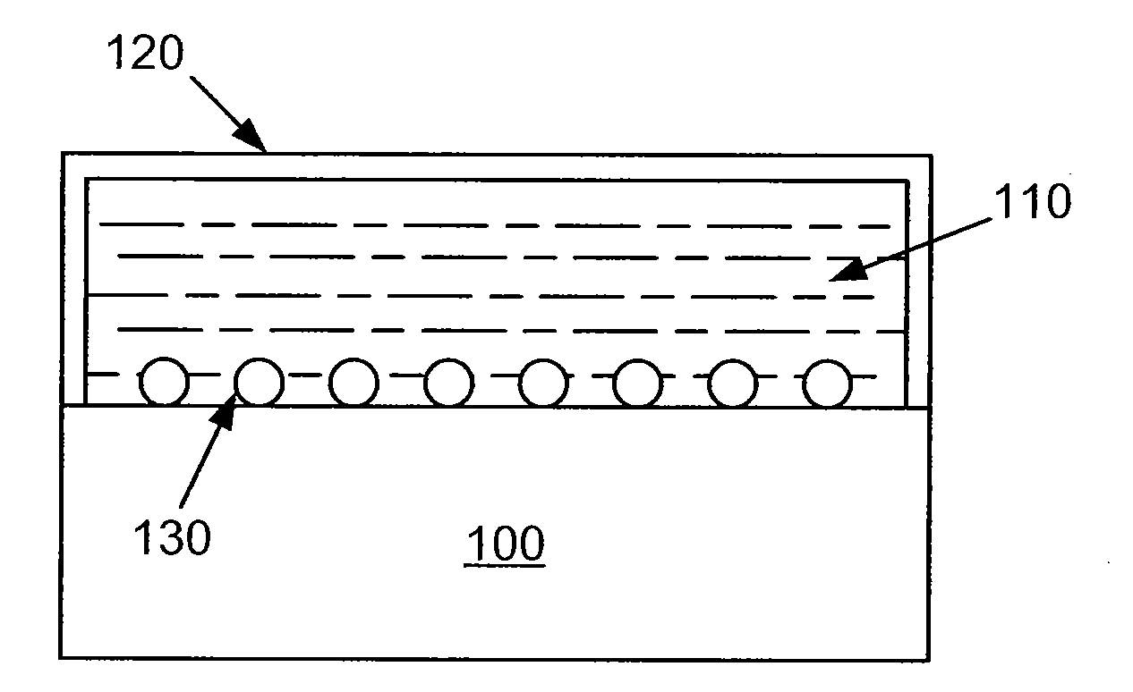
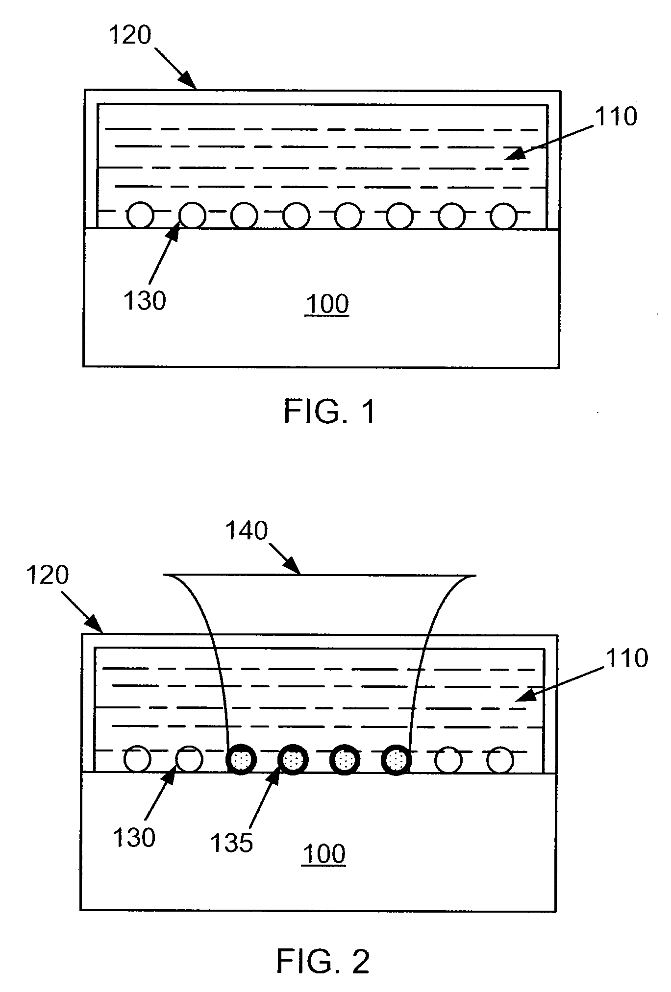
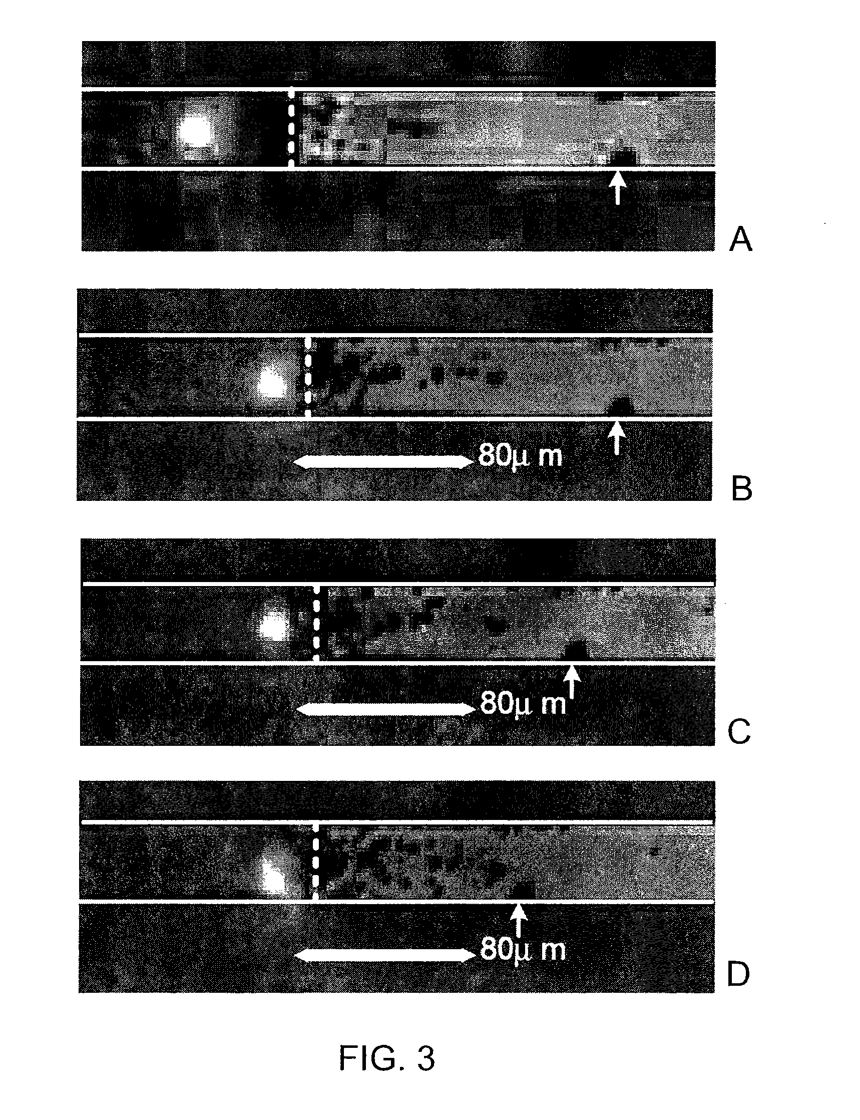
[0037]The present invention relates generally to microfluidic control techniques. In particular, the present invention provides a method of plasmon assisted optofluidics using a laser. More particularly, the present invention provides a method for optically controlling fluid in a microchannel using a plasmon resonance in fixed arrays of nanoscale metal structures to produce localized evaporation of the fluid when illuminated by a stationary, low power laser. Merely by way of example, the invention has been applied to drag the surface of the fluid, drive evaporative pumping, and provide intra-channel distillation and sample concentration, but it would be recognized that the invention has a much broader range of applicability.

[0038]Here we demonstrate a technique of plasmon assisted optofluidics (PAO) according to certain embodiments of the present invention. By incorporating plasmonic resonant structures into a microscale vessel channel, some embodiments show that plasmonic heating a...


PUM


Abstract

A method of microfluidic control via localized heating includes providing a microchannel structure with a base region that is partially filled with a volume of liquid being separated from a gas by a liquid-gas interface region. The base region includes one or more physical structures. The method further includes supplying energy input to a portion of the one or more physical structures within the volume of liquid in a vicinity of the liquid-gas interface region to cause localized heating of the portion of the one or more physical structures. The method also includes transferring heat from the portion of the one or more physical structures to surrounding liquid in the vicinity of the liquid-gas interface region and generating an interphase mass transport at the liquid-gas interface region or across a gas bubble while the volume of liquid and the gas remain to be substantially at ambient temperature.

Description

CROSS-REFERENCES TO RELATED APPLICATIONS[0001]This application claims priority of U.S. Patent Application No. 60 / 897,743, and titled “PLASMON ASSISTED CONTROL OF OPTOFLUIDICS,” filed by Adleman et al. at Jan. 26, 2007 and claims priority to U.S. Patent Application No. 60 / 966,402, and titled “METHOD FOR MICROFLUIDIC DISTILLATION AND SAMPLE CONCENTRATION,” filed by Adleman et al. at Aug. 28, 2007 commonly assigned, and each of which is incorporated by reference in its entirety.STATEMENT AS TO RIGHTS TO INVENTIONS MADE UNDER FEDERALLY SPONSORED RESEARCH OR DEVELOPMENT[0002]The U.S. Government has certain rights in this invention pursuant to Grant No. HR0011-04-1-003267 awarded by DARPA and Grant No. N00014-06-1-0454 awarded by the Office of Naval Research.REFERENCE TO A “SEQUENCE LISTING,” A TABLE, OR A COMPUTER PROGRAM LISTING APPENDIX SUBMITTED ON A COMPACT DISK[0003]NOT APPLICABLEBACKGROUND OF THE INVENTION[0004]The present invention relates generally to microfluidic control techniq...

Claims


Application Information

Patent Timeline
IPC IPC(8): F15C1/04
CPCB01L3/50273B01L2400/0454F04B19/006Y10T137/0318Y10T137/2191Y10T137/2196
Inventor ADLEMAN, JAMESBOYD, DAVID A.GOODWIN, DAVID G.PSALTIS, DEMETRI
Owner CALIFORNIA INST OF TECH
Why Eureka
Try Eureka