Laser radar projection with object feature detection and ranging

a technology of object feature detection and laser radar, applied in the field of laser projection systems, can solve the problems of time and labor, degrade precision and reliability, and prior attempts to solve this problem have not provided a solution

Active Publication Date: 2008-10-09
FARO TECH INC
View PDF35 Cites 104 Cited by
  • Summary
  • Abstract
  • Description
  • Claims
  • Application Information

AI Technical Summary

Benefits of technology

[0029]The TLRP has a high-sensitivity optical feedback from a scanned object shares the beam path of the laser output beam, through the beam steering system to the object, with the output projecting beam. The TLRP separates the output beam and the optical feedback beam while substantially suppressing unwanted prevailing background light, including the ambient light illuminating the object, from reaching a photodetector for the feedback beam. Because the optical feedback is time delayed with respect to its associated reference pulse in the present TLRP invention, the scattering generated by the output beam is out of synch with the optical feedback. This provides a degree of inherent control over the adverse impact of the scattered light on the detection of the very faint optical feedback signal pulses. The separation of the optical feedback, both optically and in time, together with other stray and scattered light suppression systems described herein, makes the weak optical feedback signal from a typical object feature distinguishable enough to enable usage of object features as fiducial points for laser projection, thereby providing the targetless laser projection.

Problems solved by technology

The requirement to place reference targets onto the object has many practical drawbacks to the process of using laser projectors.
It is time and labor consuming.
It also degrades precision and reliability due to a lack of precision in the placement and resultant position of the target Some potentially viable applications currently cannot be implemented because they do not allow any target placement on the object surface.
However, prior attempts to solve this problem have not provided a solution without other drawbacks.
A serious drawback of the Rueb arrangement is the existence of two different optical paths for laser projection and camera imaging, which necessitates for frequent mutual calibration between the camera imaging system and the laser projection system.
As a result, the suggested solution reduced accuracy.
This unwanted “stray” light renders the optical feedback signal undistinguishable.
Human errors adversely impact any manufacturing process, they are unacceptable, and they have to be revealed as soon as possible.
This system is complicated, requires use of a cage with retro-reflective targets and requires sequential usage of two separate expensive units of equipment—digitizer and projector.
Because of the need to use multiple units and multiple operations, this system is limited in its accuracy, particularly the high precision required for modern aircraft and other precision manufacturing, e.g. to ±0.015 inch at 15 feet.
Again, this solution requires separate sequential use of two very different and expensive units of equipment −3D digitizing system and 3D laser projector.
Known solutions for stand alone 3D scanning digitizers are not suitable for laser projection with feature detection.
This system, however, is quite slow and it cannot generate glowing templates as a laser projector.
It cannot provide required accuracy for the high precision edge features detection.
Also, the described system does not capture signals returned from objects well if they have a substantially variable reflectivity.
For such objects this system obtains very sparse data with low spatial resolution.
Again, the disclosed apparatus is only a digitizer; it cannot effectively generate glowing templates for laser projection.
The dynamic range of a digitizer in dealing with variations in the intensity of light returned from a scanned object is a serious practical limitation on the usefulness of known digitizers.
A polished steel ball is a particularly difficult object to scan because it produces basically a strong single point reflection surrounded by much weaker reflections.
Known scanners and known projectors do not provide anywhere near this dynamic range.
Moreover, it does not provide adequate sensitivity and dynamic range to accurately acquire a variety of conventional surfaces and 3D objects and to detect their edge features.

Method used


Image

  • Laser radar projection with object feature detection and ranging
  • Laser radar projection with object feature detection and ranging
  • Laser radar projection with object feature detection and ranging

Examples


Embodiment Construction

Targetless Object Feature Detection

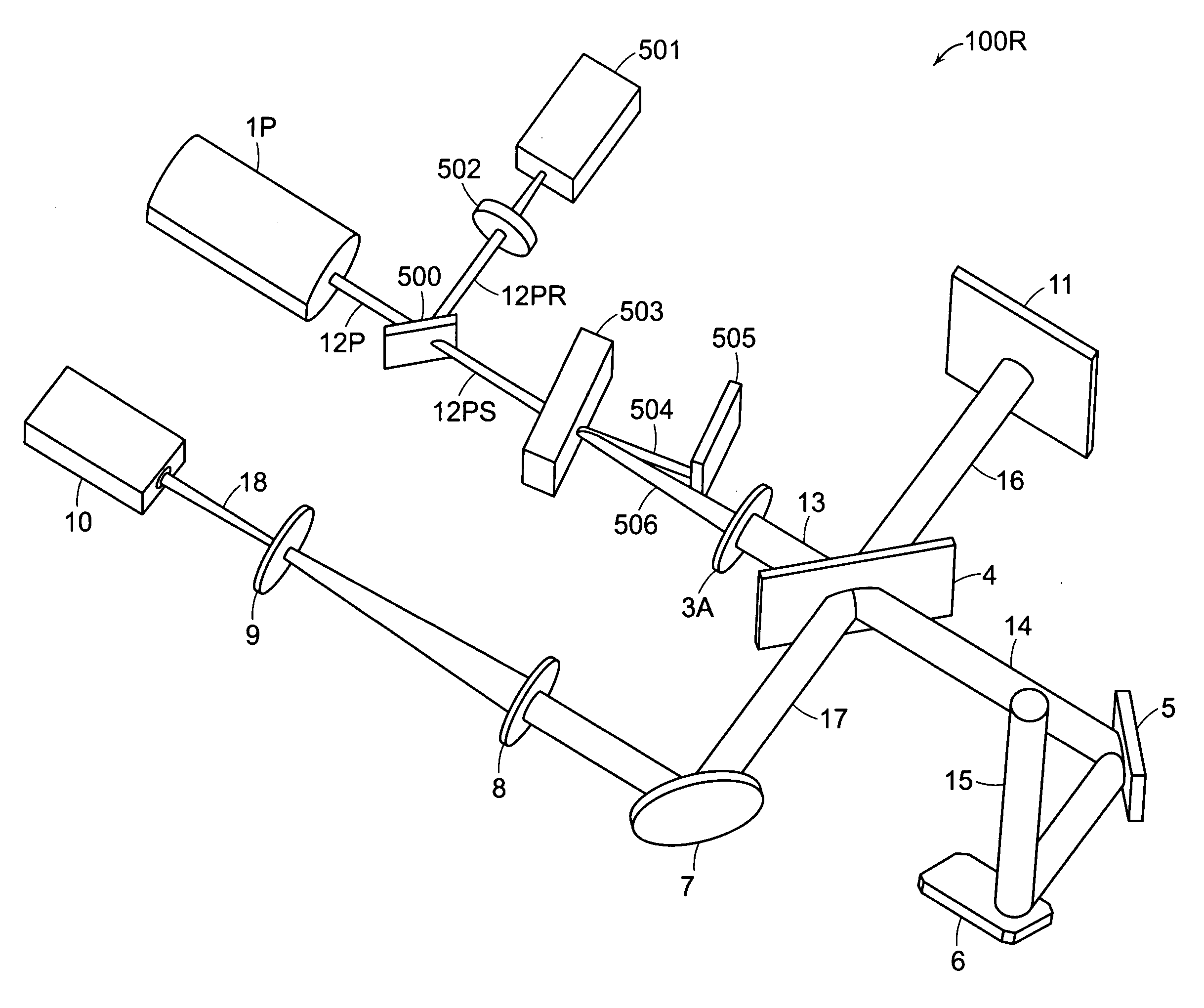
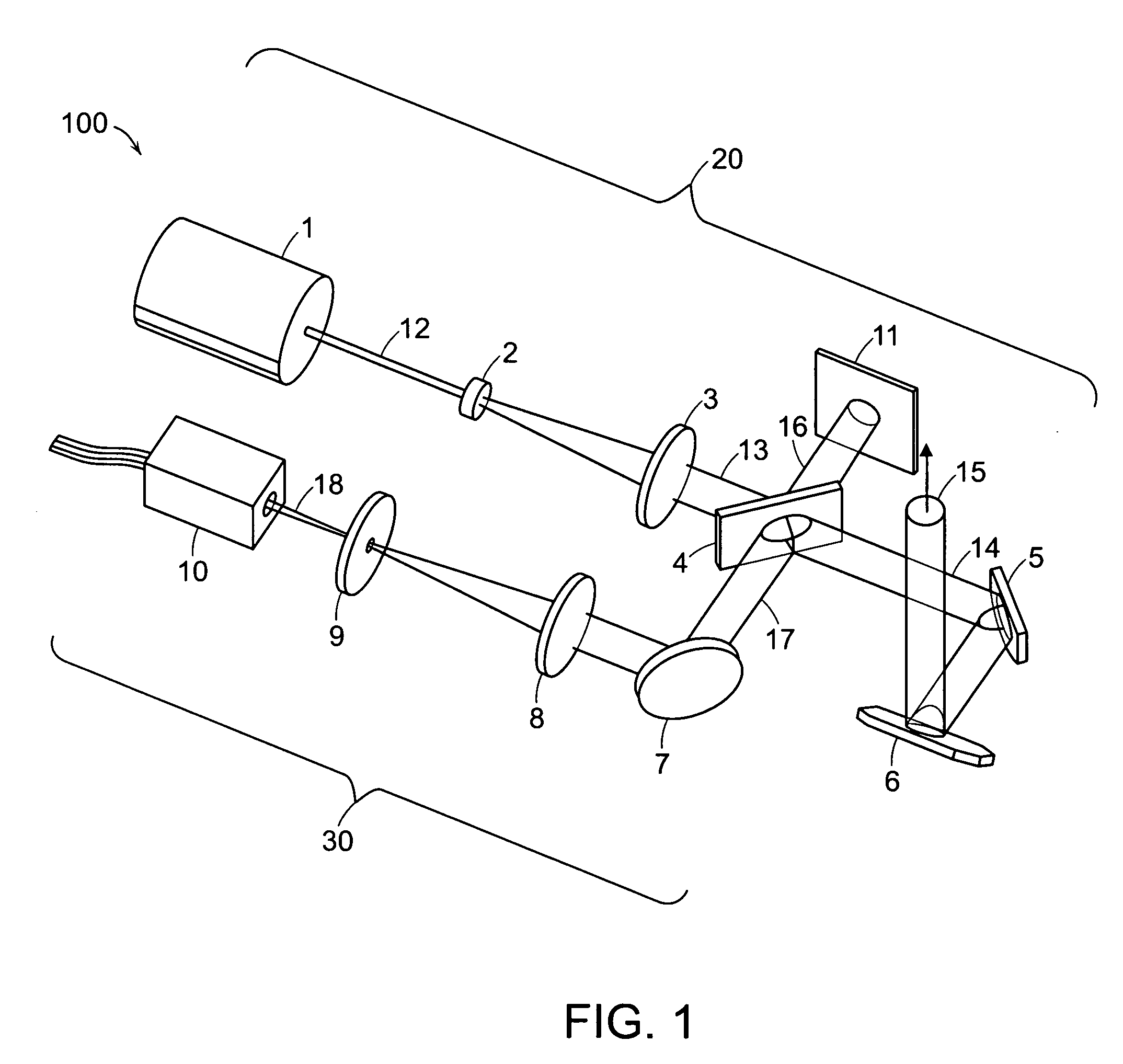
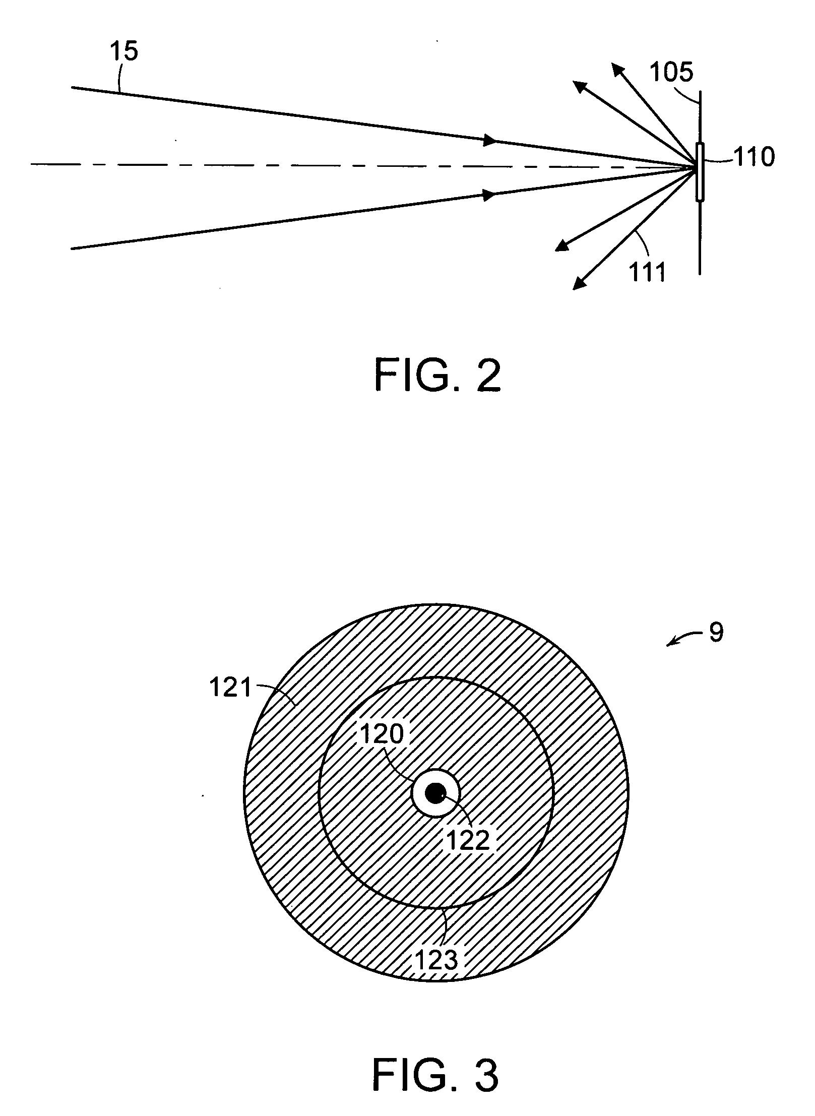
[0060]FIGS. 1-15 relate to a targetless laser projector (“TLP”) 20 as shown and described in Applicants' parent application referenced above. The laser radar projector (“LRP”) 100R of the present improvement invention is described below with reference to FIGS. 16-18. The TLP 20 has two major optical subsystems—a projection subsystem 20 and an optical feedback subsystem 30. The projection subsystem 20 includes a laser 1, beam expanding lenses 2 and 3, a beam splitter 4, a beam dump 11, and beam steering mirrors 5 and 6. The beam steering mirrors are mounted on shafts of corresponding galvanometers 203, 204 in FIG. 6, as is well known in the laser projection art. The optical feedback subsystem 30 includes a mirror 7, a focusing lens 8, a spatial filter 9, and a high-sensitivity photo detector 10.

[0061]The laser 1 emits a laser beam 12. The laser 1 is typically a solid state diode pumped laser that produces light at the “green” wavelength of 532 nanom...


PUM


Abstract

A 3D pulsed laser projection system scans an object to produce a dense 3D point cloud and projects a laser light beam onto an object as a glowing template. A high-sensitivity optical feedback system receives and detects a feedback beam of the output beam light diffusely reflected from the object. The feedback light and projected beam share the same beam path between steering mirrors and the object. A light suppression component controls stray scattered light, including ambient light, from being detected. A time-of-flight measurement subsystem provides a distance-to-object measurement for projected pulses. An acousto-optical modulator, variable gain detected signal amplification and variable photo-detector power together produce a dynamic range for detected reflected feedback signals of at least 100,000, and up to 500,000. Optical fiber cables spatially filter scattered light and isolate the photo-detectors thermally. The laser is preferably pulsed at least 50 kHz, with sampling of the projected and feedback reflected optical pulse signals at a sampling rate of up to 10 gigasamples per second.

Description

CROSS-REFERENCE TO RELATED APPLICATIONS[0001]This application is a continuation-in-part of, and claims priority under 35 USC 120 of, U.S. patent application Ser. No. 11 / 345,784 filed Feb. 1, 2006 issuing Dec. 11, 2007 as U.S. Pat. No. 7,306,339, the disclosure of which is incorporated herein by reference, and also claims priority under 35 USC 119(e) of U.S. Provisional Patent Application No. 60 / 649,241 filed on Feb. 1, 2005, the disclosure of which is also incorporated herein by reference.FIELD OF THE INVENTION[0002]This invention relates to laser projection systems, and in particular to a laser projection system that projects a glowing template light pattern on an object without requiring retro-reflective or cooperative targets and provides 3D location and light reflectivity information about points on the object to pixels with high precision, sensitivity, and dynamic range.BACKGROUND OF THE INVENTION[0003]Laser projectors are widely used in manufacturing processes to assist in pre...

Claims


Application Information

Patent Timeline
Patent Type & Authority Applications(United States)
IPC IPC(8): G01C3/08
CPCG01B11/2518G01N21/4738G01N21/9515G01N21/95623G01N2021/8411G01N2021/8472G01N2201/0642G02B26/101G02B27/2292G03B21/00G03B21/28G03B35/18G06T7/0057H04N9/3129H04N9/3185H04N9/3194G03B21/005G06T7/521G02B30/56
Inventor KAUFMAN, STEVEN P.SAVIKOVSKY, ARKADYCHAGARIS, CHRISTOPHER C.STAVE, JOEL
Owner FARO TECH INC
Why Eureka
Try Eureka