Anti-reflection coating with low resistivity function and transparent conductive coating as outermost layer

a technology of resistivity function and anti-reflection coating, which is applied in the field of multi-layer systems, can solve the problems of slowing down the application of anti-reflection coating in high volume production, difficult to make electrical contact with the buried ito layer that is isolated by the outermost siosub>2/sub>layer, and achieve good electrical conductive properties. , the effect of reducing the amount of work

Inactive Publication Date: 2008-10-09
INNOVATION & INFINITY GLOBAL
View PDF14 Cites 7 Cited by
  • Summary
  • Abstract
  • Description
  • Claims
  • Application Information

AI Technical Summary

Benefits of technology

[0024]Because the surface layer has good electrical conductive properties, the layer system reduces much of the work in the grounding process and also increases the total yield and reliability in high volume production. The present invention provides a surface conductive layer structure with an anti-reflection coating that can be applied to the LCD and PDP display industries for glass and plastic film substrates.

Problems solved by technology

However, when we apply the anti-reflection coating on a display screen to create an anti-static effect for a computer monitor, or low reflection glass for an LCD or a PDP, there are some bottlenecks in the process for high volume mass production.
However, a troubling phenomenon is that if the surface material of the conventional optical layer structure is SiO2, the typical thickness of the SiO2 layer is about 1000 Å. The material characteristic of SiO2 is that it has a high density, inert properties in chemicals and is a very good insulating layer for electricity.
In the process of applying a conventional anti-reflection coating to a display screen, it is difficult to make an electrical contact with the buried ITO layer that is isolated by the outermost SiO2 layer.
This process slows down the application of anti-reflection coating in high volume production.
Alternatively, an ultra-sonic welding process produces small and bright contamination because of the liquid tin, and the explosive energy of the ultra-sonic process.
This process also produces inconsistent contact resistance for each bus bar line because the ultrasonic-welding process cannot consistently break the insulating coating at the same depth evenly and obtain a uniform contact resistance with the ITO layer.
The drawbacks mention above will reduce the yield and reliability of the manufacturing process for the application of conventional anti-EMI and anti-reflection coating.

Method used


Image

  • Anti-reflection coating with low resistivity function and transparent conductive coating as outermost layer
  • Anti-reflection coating with low resistivity function and transparent conductive coating as outermost layer
  • Anti-reflection coating with low resistivity function and transparent conductive coating as outermost layer

Examples


Embodiment Construction

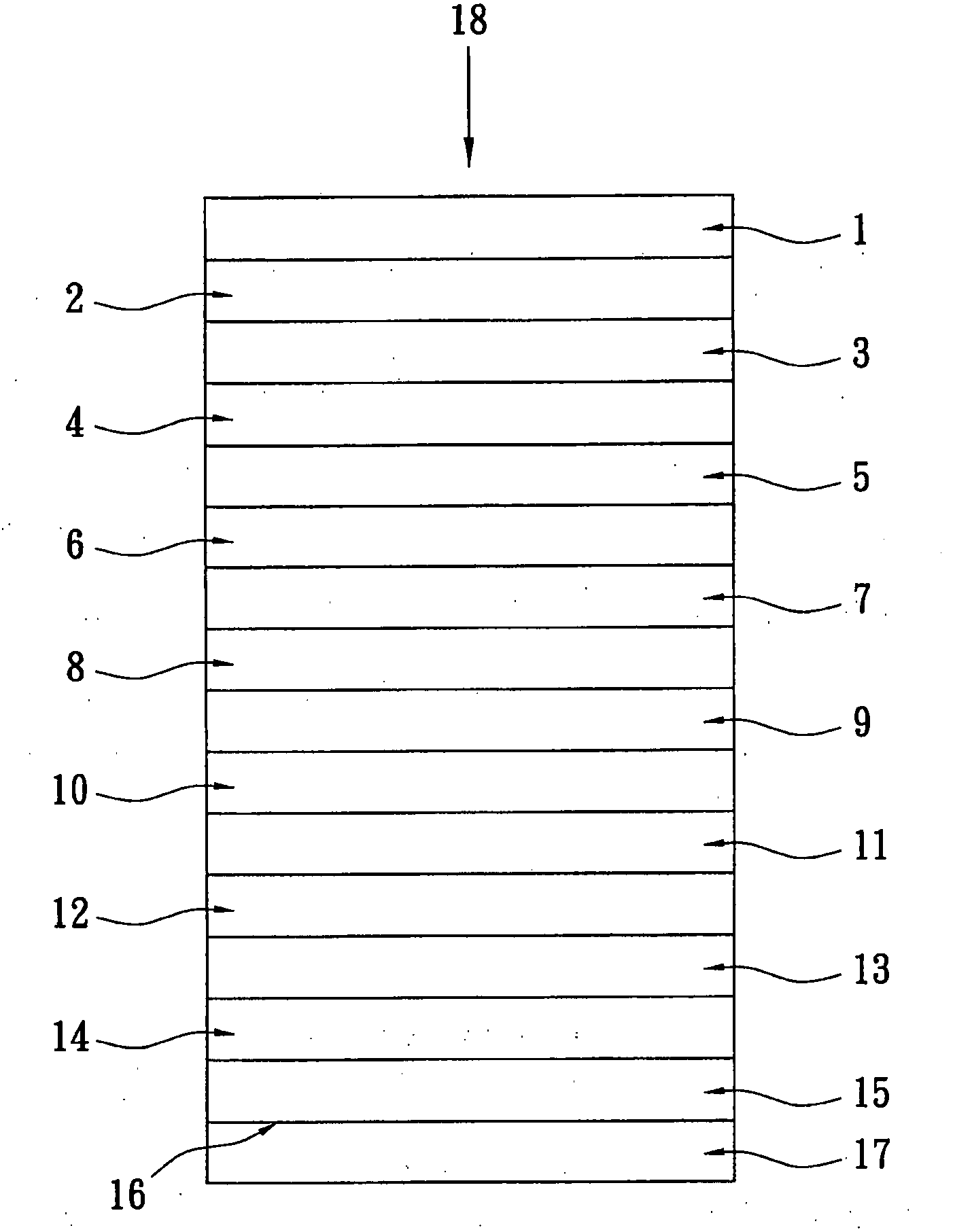
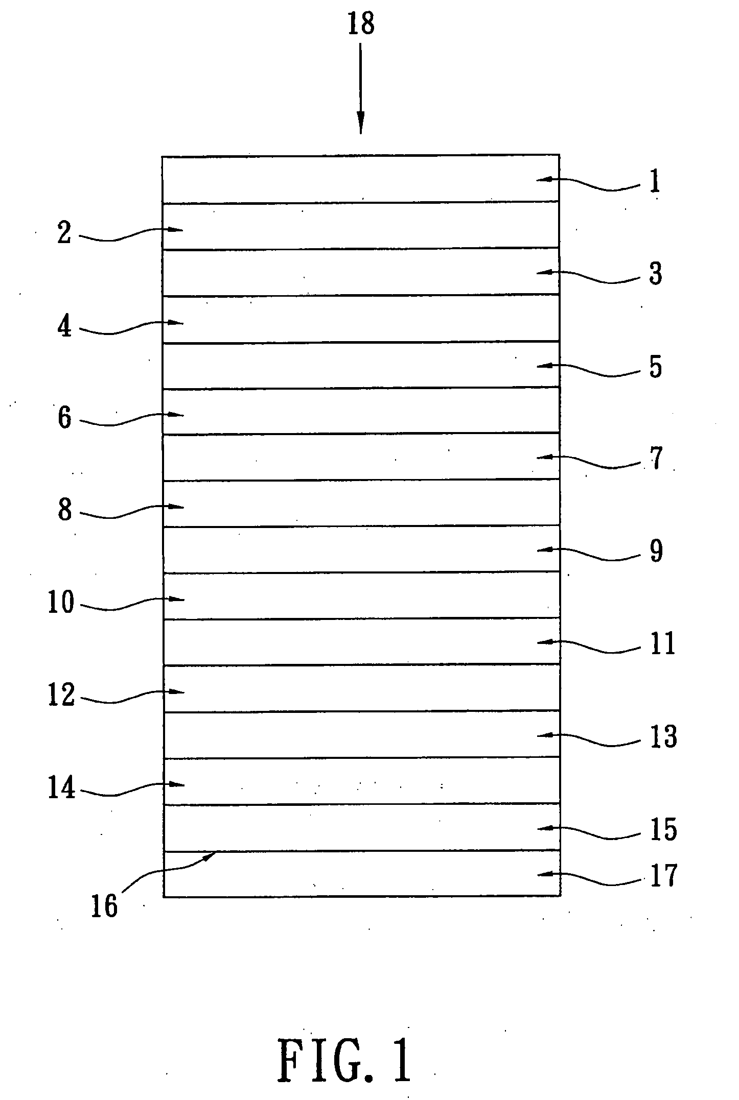
[0045]The present invention relates to an oxide based anti-reflection coating with 15 layers. The thickness value of each layer is specified as either a physical thickness in nm, as an optical thickness in the form of a fraction, or as a multiple of a wavelength of visible light. The typical value is 520 nm.

[0046]Reference is made to FIG. 1. A substrate 17 is composed of glass, a plastic film, or other transparent materials. A front surface 16 of the substrate 17 is that side of the substrate 17 that is facing the observer. An arrow 18 indicates the direction of viewing. A layer, which contacts the front surface 16 of the substrate 17, is named a fifteenth layer 15. In the direction the observer follows, the fourteenth layer 14 is arranged on the fifteenth layer 15, which is next to the front surface of the substrate 17. The thirteenth layer 13 is arranged on the fourteenth layer 14. The twelfth layer 12 is arranged on the thirteenth layer 13. The eleventh layer 11 is arranged on th...


PUM

PropertyMeasurementUnit
thicknessaaaaaaaaaa
thicknessaaaaaaaaaa
thicknessaaaaaaaaaa

Abstract

An anti-reflection coating anti-reflection coating with low resistivity function and transparent conductive coating as outermost layer is disclosed. The anti-reflection coating contains a transparent conductive oxide as a surface layer and has a photo reflectance below 0.5%. The resistivity of the anti-reflection coating is between 0.5Ω and 0.7Ω per square, and its transparency is between 55% and 70%.

Description

BACKGROUND OF THE INVENTION[0001]1. Field of the Invention[0002]The present invention relates to an anti-reflection coating with a low resistivity function and a transparent conductive coating which can be used as an as outermost layer. In particular, this invention relates to a multi-layer system that has a high anti-reflection effect.[0003]2. Description of the Related Art[0004]An anti-reflection multi-layer system is usually used as a plastic substrate, a glass substrate, or a plastic web. A great number of multi-layer systems have previously been disclosed.[0005]U.S. Pat. No. 4,921,760 discloses a multi-layer anti-reflection coating with excellent adhesion between the CeO2 layer and the synthetic resin. The layer system includes CeO2, Al2O3, ZrO2, SiO2, TiO2, and Ta2O5. All the thin films of the layer system are oxide materials. There are 3 to 5 thin layers in the layer system. For example, the total thickness of the 5-layered structure is about 3580 angstroms. The material of t...

Claims


Application Information

Patent Timeline
Patent Type & Authority Applications(United States)
IPC IPC(8): C09K19/00B32B17/06C23C14/00B32B9/00
CPCG02B1/115Y10T428/10Y10T428/24942Y10T428/265Y10T428/24975C09K2323/00
Inventor CHANG, CHENG-CHIEH
Owner INNOVATION & INFINITY GLOBAL
Why Eureka
Try Eureka