
Low-stress hermetic die attach

Inactive Publication Date: 2008-10-16
HONEYWELL INT INC
View PDF11 Cites 48 Cited by
  • Summary
  • Abstract
  • Description
  • Claims
  • Application Information

AI Technical Summary

Benefits of technology

[0006]This invention relates generally to the attachment of stress-sensitive die in hermetic packages and, more specifically, to methods and systems

Problems solved by technology

Scale factor thermal hysteresis and drift of MEMS gyro sensors and MEMS accelerometers, when packaged in a leadless ceramic chip carrier (LCCC) alumina (Al2O3) package, are problematic.
Experiments have shown that thermomechanical stress imposed on the gyro or accelerometer by the package is one source of this thermal hysteresis and drift.
The bending of the die causes small changes in the gaps of some capacitors on the die, which changes the scale factor of the sensors.
These thermomechanical stresses can cause both a scale factor hysteresis with temperature and a scale factor drift with time as a result of plastic deformation of the gold bump die attachment or plastic deformation of the package-to-PWB solder joints.
It is known that the problem of die sensitivity to package stress is shared by many other MEMS and non-MEMS devices.
Examples of stress-sensitive non-MEMS functions include: Infrared (IR) sensors made of various materials, whose softness can lead to damage as a result of package stress; Gallium Arsenide (GaAs) integrated circuits, whose softness can lead to damage as a result of package stress; and some silicon analog circuits whose parameters may be affected by stress-induced changes in MOS transistor conductances, bipolar gains, or resistor values.
With respect to MEMS accelerometers and gyros, more conventional means cannot be used to reduce thermomechanical stress on the die because they are either not compatible with hermeticity or are sensitive to vibration and / or high-g forces.

Method used


Image

  • Low-stress hermetic die attach
  • Low-stress hermetic die attach
  • Low-stress hermetic die attach

Examples


Embodiment Construction

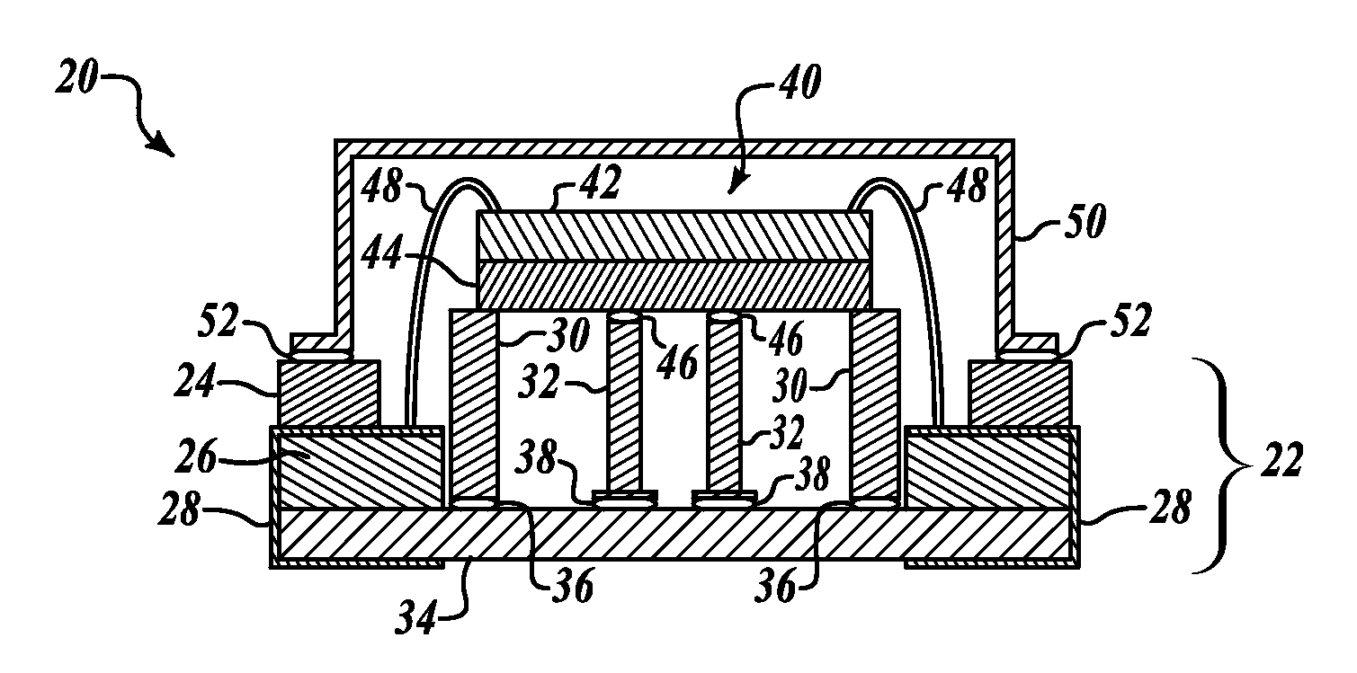
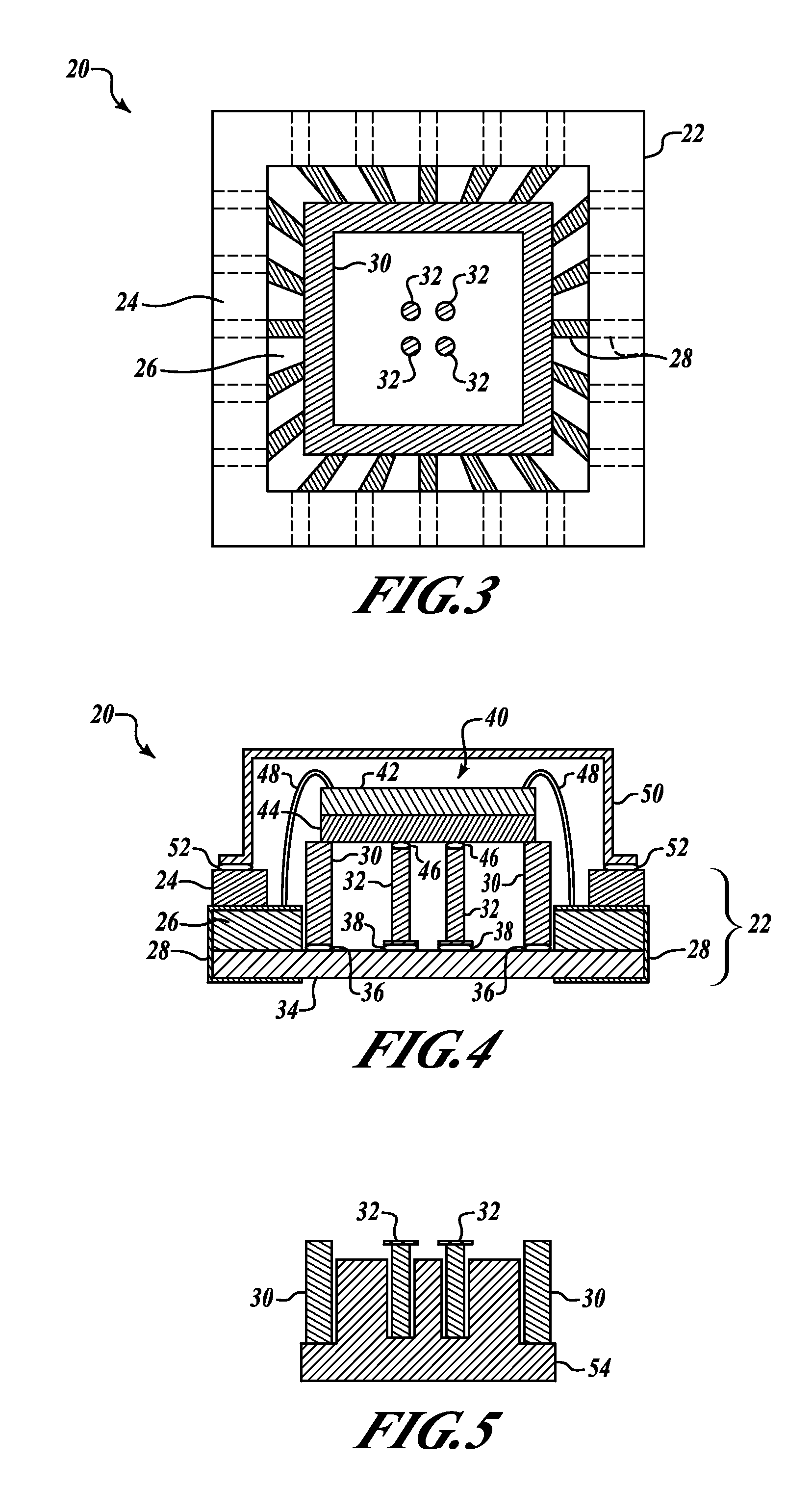
[0022]FIGS. 3 and 4 are diagrams showing a top partial x-ray view and a side cross-sectional view respectively of a device 20 formed in accordance with an embodiment of the invention. The device 20 includes a die 40 supported by a plurality of die attach columns 32 located in a package 22. The die attach columns 32 reduce thermomechanical stress and bending effects on the die 40 caused by a mismatch of temperature coefficients of expansion between the die 40 and the package 22. The device 20 also includes a stress relief ring 30 that is used to relieve stress during the attachment of one or more wires 48 between the die 40 and a plurality of package interconnect pins 28.

[0023]The device 20 includes the package 22 that is formed of layers of ceramic tape co-fired to bond together in an example embodiment of the invention. The package 22 includes a first layer 24 and a second layer 26 as shown in FIG. 3. The ceramic tape may be made of aluminum oxide, aluminum nitride, sintered alumin...


PUM


Abstract

A low-stress hermetic die attach apparatus is disclosed. An example apparatus includes a hermetic package, a device disposed within the hermetic package, and one or more elongated structures greater than 2 thousandths of an inch (mils) in length connected to the package at one end and to the device at the other end. In some embodiments, the apparatus includes elongated structures at least 30 mils long or at least 100 mils long and the device includes a microelectromechanical system (MEMS) die that includes accelerometer or gyro components. In some embodiments, the elongated structures include a column or a pin made of an alloy material such as Kovar. In one embodiment, the Kovar pin is gold plated, attached to the package with a high temperature solder, and attached to the die using gold stud bumps.

Description

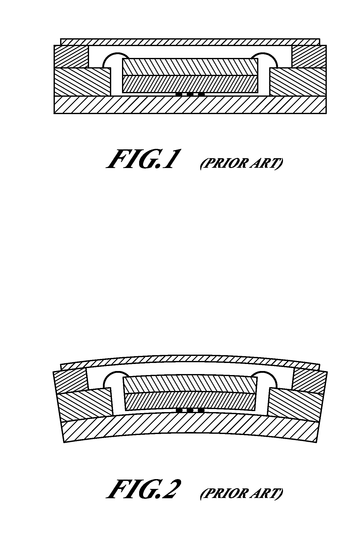
BACKGROUND OF THE INVENTION[0001]Scale factor thermal hysteresis and drift of MEMS gyro sensors and MEMS accelerometers, when packaged in a leadless ceramic chip carrier (LCCC) alumina (Al2O3) package, are problematic. Experiments have shown that thermomechanical stress imposed on the gyro or accelerometer by the package is one source of this thermal hysteresis and drift. The thermomechanical stress is caused by a mismatch of the temperature coefficients of expansion (CTE or TCE) between a sensor die (3.6 ppm / ° C.) and the alumina package (6.8 ppm / ° C.). This stress causes the die to bend while cooling down from 320° C. (the die attachment temperature) to room temperature (25° C.), or while temperature cycling over the range of −55° C. to +85° C. FIG. 1 is a diagram showing a prior art MEMS die gold-bumped into an LCCC package while still at the gold bump die attach temperature of approximately 320° C. After attachment, the gold bumps are typically approximately 3-10 mils in diamete...

Claims


Application Information

Patent Timeline
IPC IPC(8): H01L29/84
CPCH01L21/50H01L23/057H01L23/10H01L23/562H01L24/45H01L24/83H01L24/85H01L2224/32014H01L2224/32506H01L2224/45124H01L2224/45144H01L2224/45147H01L2224/48091H01L2224/48227H01L2224/83194H01L2224/83801H01L2224/8385H01L2224/8389H01L2224/85H01L2924/01013H01L2924/01014H01L2924/01027H01L2924/01028H01L2924/01029H01L2924/01042H01L2924/0105H01L2924/01074H01L2924/01077H01L2924/01079H01L2924/01082H01L2924/01322H01L2924/07802H01L2924/09701H01L2924/10329H01L2924/14H01L2924/15153H01L2924/1517H01L2924/16152H01L2924/16195H01L2924/19041H01L2924/19043H01L2924/3511H01L2924/0132H01L24/29H01L24/32H01L24/48H01L2224/2919H01L2224/83805H01L2924/00014H01L2924/01006H01L2924/01043H01L2924/014H01L2924/0665H01L2224/29111H01L2224/13144H01L2924/13091H01L2924/1461H01L2224/78H01L2924/00H01L2924/01032H01L2924/01031H01L2924/01033H01L2224/85203
Inventor BELT, RONALD A.MORTENSON, DOUG P.
Owner HONEYWELL INT INC
Learn More