Electrical Power Switching With Efficient Switch Protection

a technology of switch protection and electric power switching, applied in the direction of circuit arrangement, circuit arrangement resposes to fault current, pulse technique, etc., can solve the problems of power modulators, capacitors to be designed with very low stress and hence a very low energy density, laborious and dangerous work

Active Publication Date: 2008-10-16
SCANDINOVA SYSTEMS AB
View PDF11 Cites 18 Cited by
  • Summary
  • Abstract
  • Description
  • Claims
  • Application Information

AI Technical Summary

Benefits of technology

[0021]It is a general object of the present invention to be able to protect the switch(es) in a power-switching system of an electrical power system from load faults and the like.
[0022]In particular it is desirable to protect the switch(es) from load short-circuits.
[0023]It is also an object of the invention to be able to protect the switch(es) from an open-circuit load fault.
[0024]It is a specific object to retain the advantages of modem power modulator circuits based on electronically on-off controllable switches while eliminating the problem of destructive load fault currents and / or voltage spikes.

Problems solved by technology

This is laborious and dangerous work, as it must be done with high voltage applied to the PFN.
Also, fully charging and fully discharging all the PFN capacitors for each pulse, several hundred to several thousand times per second, puts a heavy strain on the dielectric material in these capacitors, and this forces the capacitors to be designed with very low stress and hence a very low energy density.
All conventional power modulators that are based on high-voltage PFN switches, such as a thyratron or silicon-controlled rectifier switch, have a problem if a short circuit occurs at the load (as happens frequently with magnetron tubes for example).
These modulators can not be turned off during the pulse, and very large fault currents can develop that sometimes damage both the modulator (particularly the switches) and the load.
Although the LCW modulator constitutes a significant advance in modulator technology, there is a price for the above advantages.
However, interrupting high currents generally shortens the lifetime of IGBTs in an unpredictable way.

Method used


Image

  • Electrical Power Switching With Efficient Switch Protection
  • Electrical Power Switching With Efficient Switch Protection
  • Electrical Power Switching With Efficient Switch Protection

Examples


Embodiment Construction

[0065]Throughout the drawings, the same reference characters will be used for corresponding or similar elements.

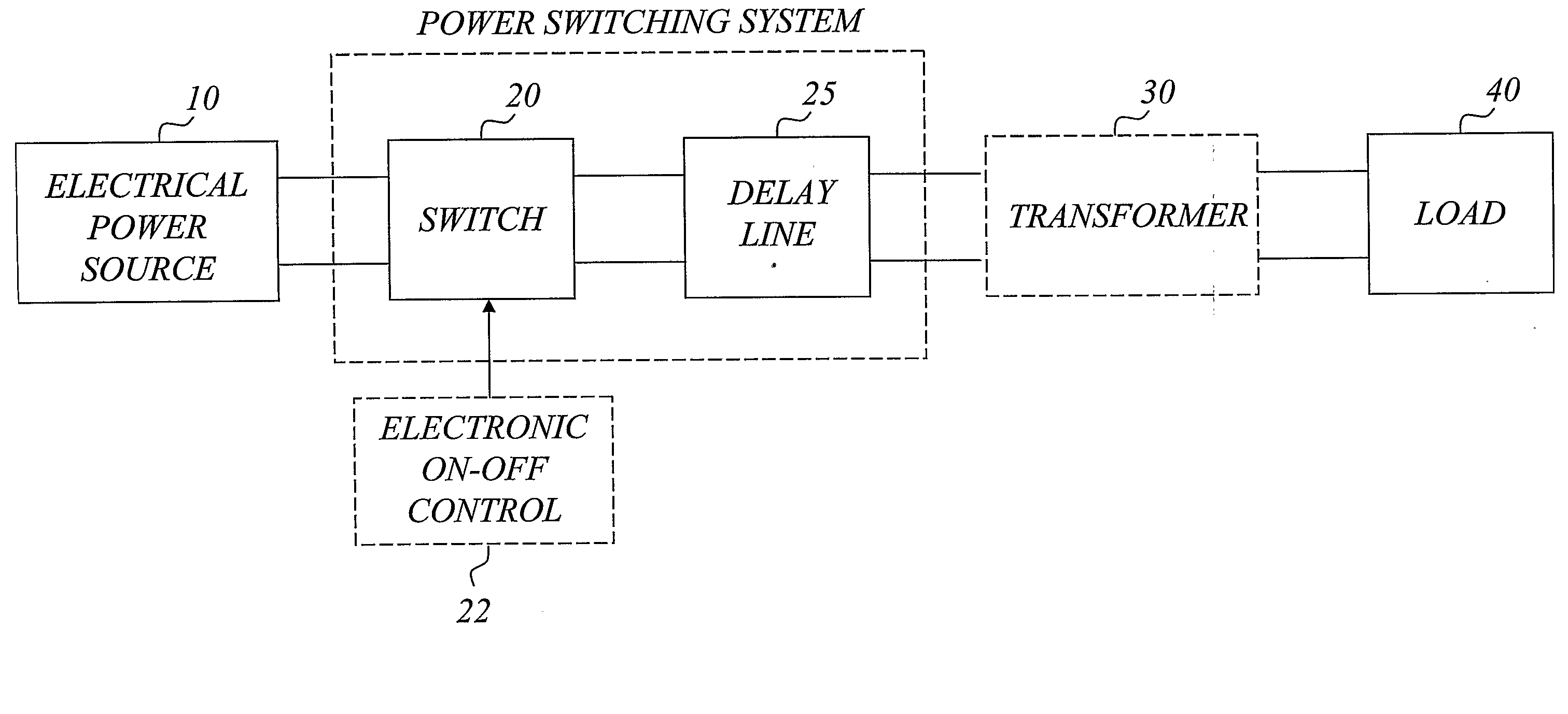
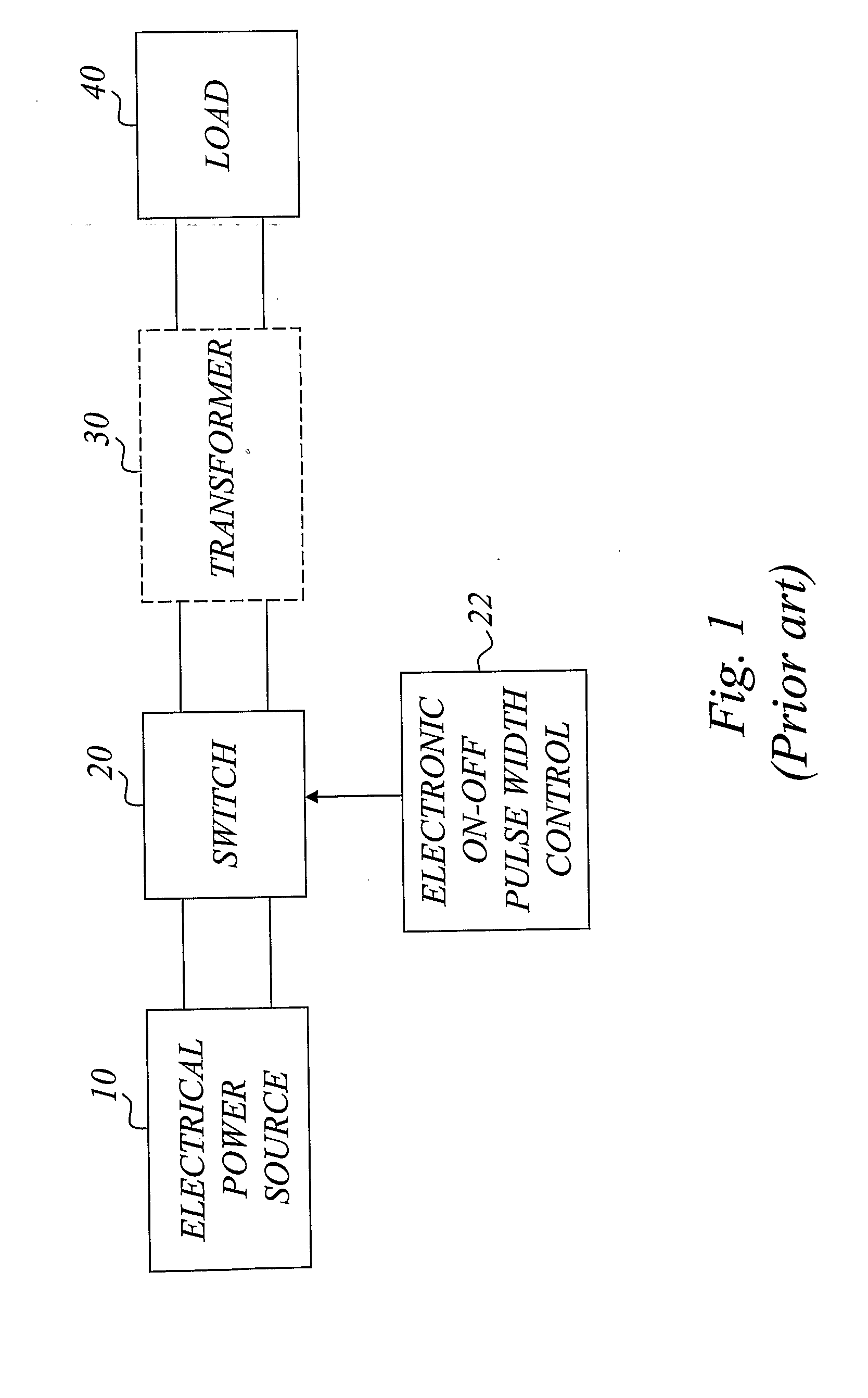
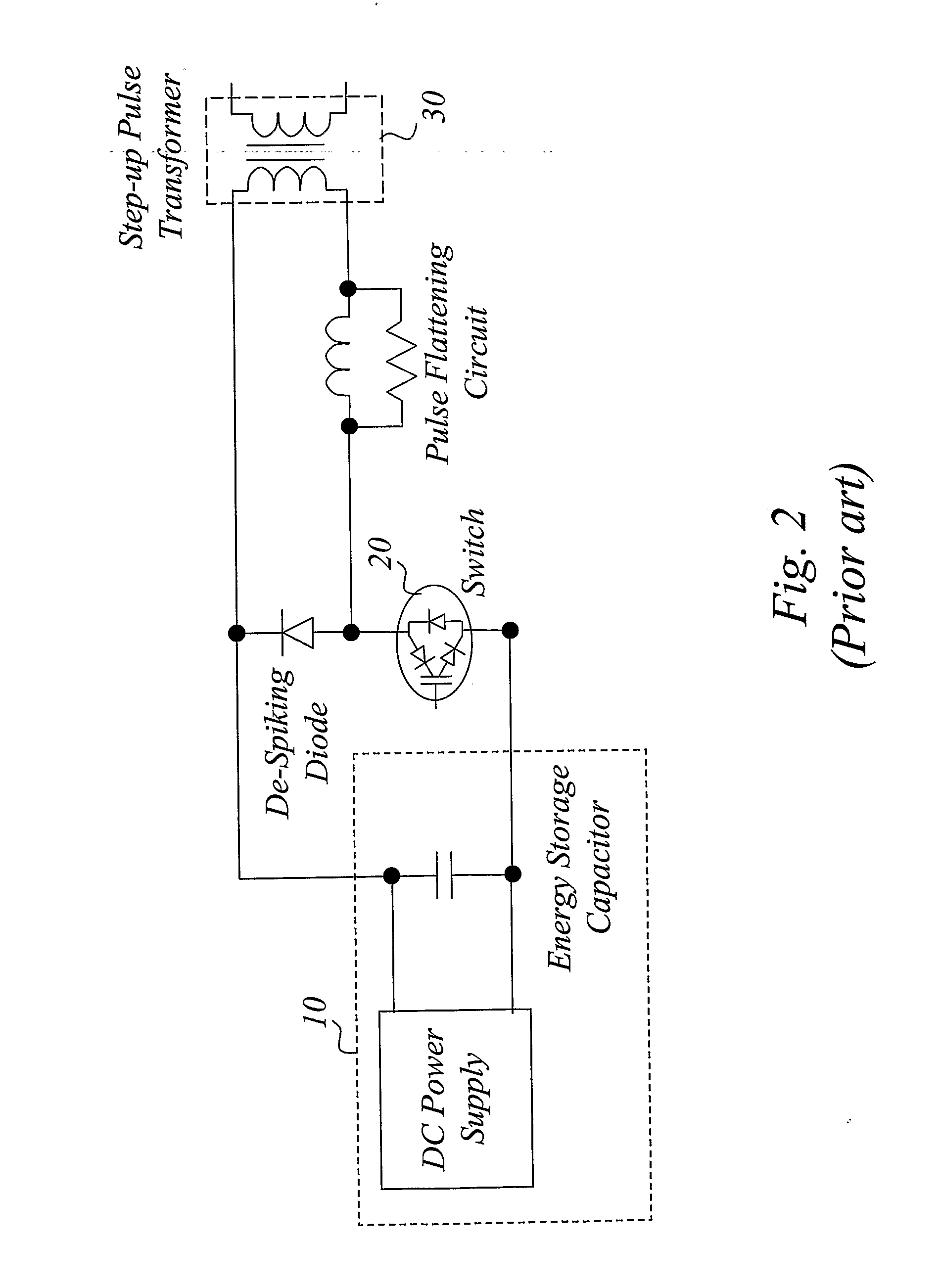
[0066]It may be useful to start with a brief analysis of the basic underlying problem. As mentioned in the background section, the LCW type power modulator offers a number of advantages compared to PFN-based power modulator systems. However, there is a price for these advantages. The simple and direct connection between a charged capacitor and the load exposes the switch of a LCW-type modulator to possibly destructive currents and voltages in case the load becomes a short-circuit. This does occur, e.g. in many microwave modulator systems, as the load (e.g. a klystron or magnetron vacuum tube) can and does spark over during the pulse at unpredictable times. The inventors have recognized that in the event of a load short-circuit the only recourse is to turn off the switch(es) as rapidly as possible. But solid-state switches have a non-zero turn-off delay time. For an IGBT sw...


PUM


Abstract

A basic idea of the invention is to introduce a transmission delay line between the switch and the power output side of a power switching system so that any sparking of the load is hidden from the switch by the time delay of the transmission line. This makes it possible to detect the load spark and actively protect the switch, typically by turning the switch off, before it actually knows that there has been a load fault spark. Alternatively, the delay of the transmission line is long enough so that the switch has already been turned off in normal pulse operation before the load fault current reaches the switch. Either way, the switch will be turned off under normal current flow and will not be subject to destructive over-current or over-voltage conditions.

Description

TECHNICAL FIELD OF THE INVENTION[0001]The present invention generally relates to electrical power systems such as power generators, power modulators and the like, and more particularly to the issue of power switching in such systems and protection of the switches.BACKGROUND OF THE INVENTION[0002]Electrical power systems can be found in virtually all industrial areas, and they normally involve some form of power switching equipment for controllably transferring electrical power or energy to the intended load. Electrical power switching is used in a wide variety of applications such as locomotive traction, automobiles, conveyor systems, escalators and elevators, air conditioning equipment, appliances, microwave systems, medical equipment, laser drivers and radar applications.[0003]A particular example of a commonly used power system is a power modulator, which can be regarded as a device that controls the flow of electrical power. When a power modulator is designed for generating elec...

Claims


Application Information

Patent Timeline
Patent Type & Authority Applications(United States)
IPC IPC(8): H02H3/16H03KH03K3/57H03K17/082
CPCH03K3/57H03K17/082
Inventor CREWSON, WALTERKALLENBORN, MARK H.
Owner SCANDINOVA SYSTEMS AB
Why Eureka
Try Eureka