
Porous bi-tubular solid state electrochemical device

a solid-state electrochemical and porous tubular technology, applied in the direction of electrochemical generators, cell components, cell component details, etc., can solve the problems of less power density, substantial resistive power loss, and general recognition of significant safety and reliability problems, so as to improve the performance life, reduce the operation temperature, and increase the strength

Inactive Publication Date: 2008-10-16
RGT UNIV OF CALIFORNIA +1
View PDF28 Cites 16 Cited by
  • Summary
  • Abstract
  • Description
  • Claims
  • Application Information

AI Technical Summary

Benefits of technology

The present invention is a bi-tubular solid state electrochemical device that includes a first porous, sintered support tube and a second porous, sintered tubular member. The first tube has layers of a first porous electrode, a dense electrolyte, and a second porous electrode, while the second tube has layers of a first porous electrode, a dense electrolyte, and a second porous electrode. The device can be used as a solid oxide fuel cell. The technical effects of the invention include improved performance and durability of the device, as well as simplified manufacturing processes.

Problems solved by technology

Planar SOFC devices are theoretically more efficient than tubular devices but are generally recognized as having significant safety and reliability issues due to the complexity of sealing and manifolding a planar stack.
Tubular SOFC devices are generally believed to be more easily implemented than planar but tubular designs provide less power density than planar devices due to their relatively long current path that result in substantial resistive power loss.
Each of these designs has disadvantages in providing acceptable fuel cells, such as SOFCs, which are low-cost, reliable, devices having excellent structural stability at high temperatures, e.g., 800° C. and overcome the start-up and load-following problems related to material failures caused by severe thermal cycling of the prior art designs.
Consequently, these fuel cells have higher resistance and are slower to start.
They also are more expensive to manufacture
Cathode-supported SOFC are typically expensive to manufacture and suffers from high ohmic loses due to long current path along the circumference of the cathode tube.
The electrical connections among anode-supported fuel cells are more difficult.

Method used


Image

  • Porous bi-tubular solid state electrochemical device
  • Porous bi-tubular solid state electrochemical device
  • Porous bi-tubular solid state electrochemical device

Examples


Embodiment Construction

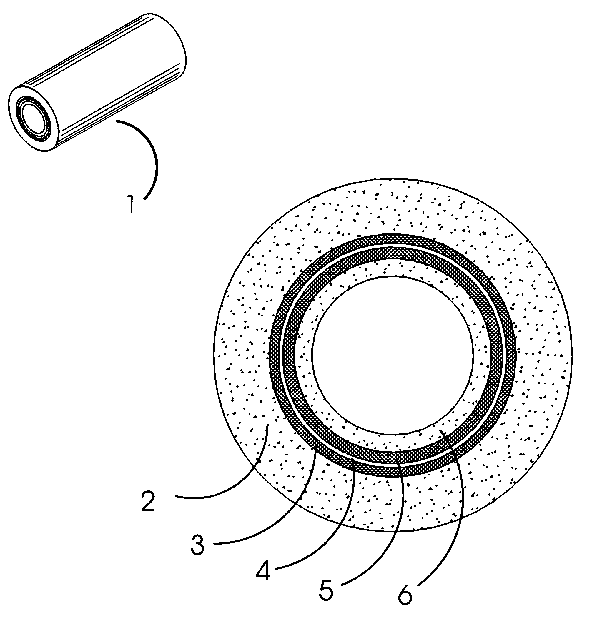
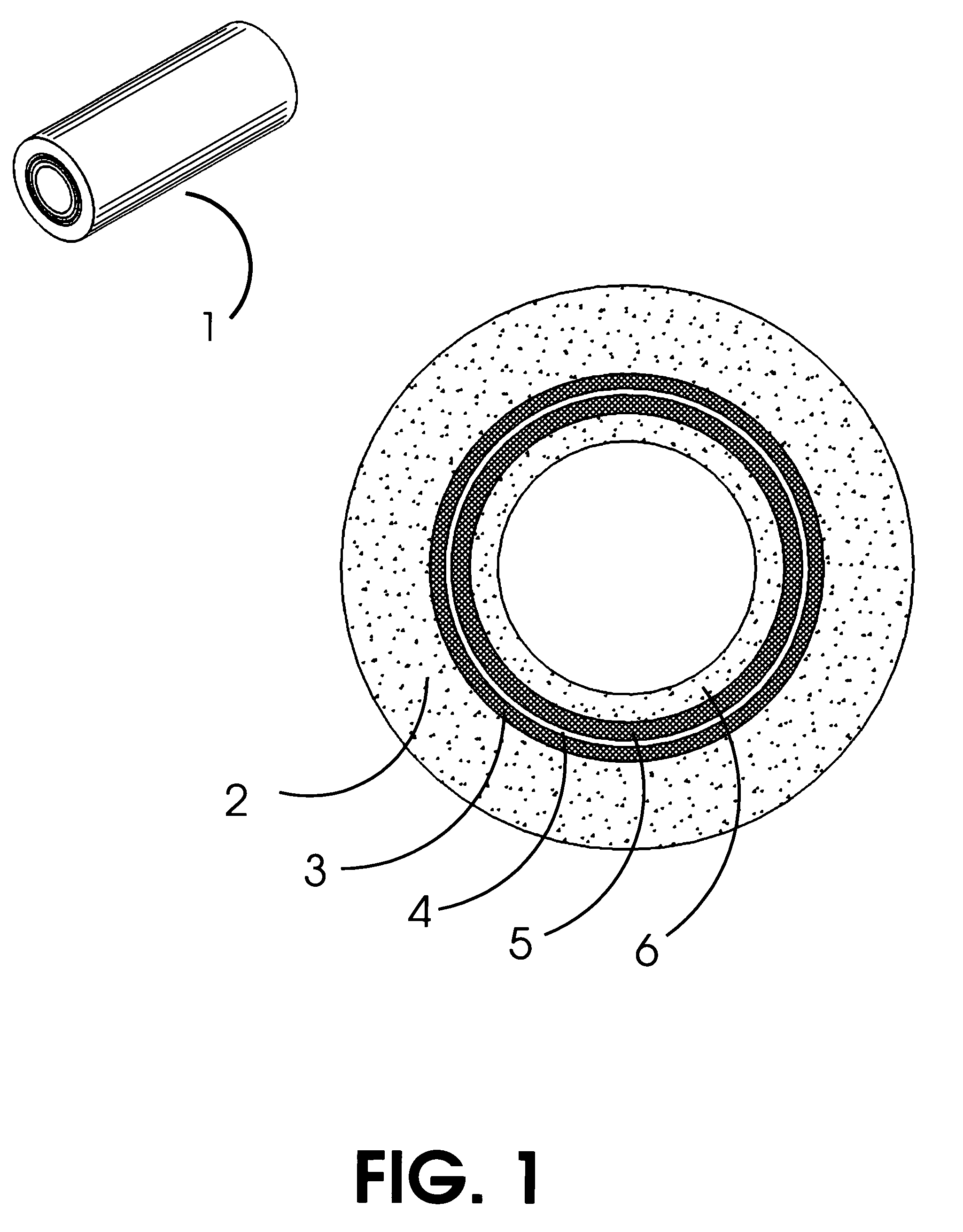
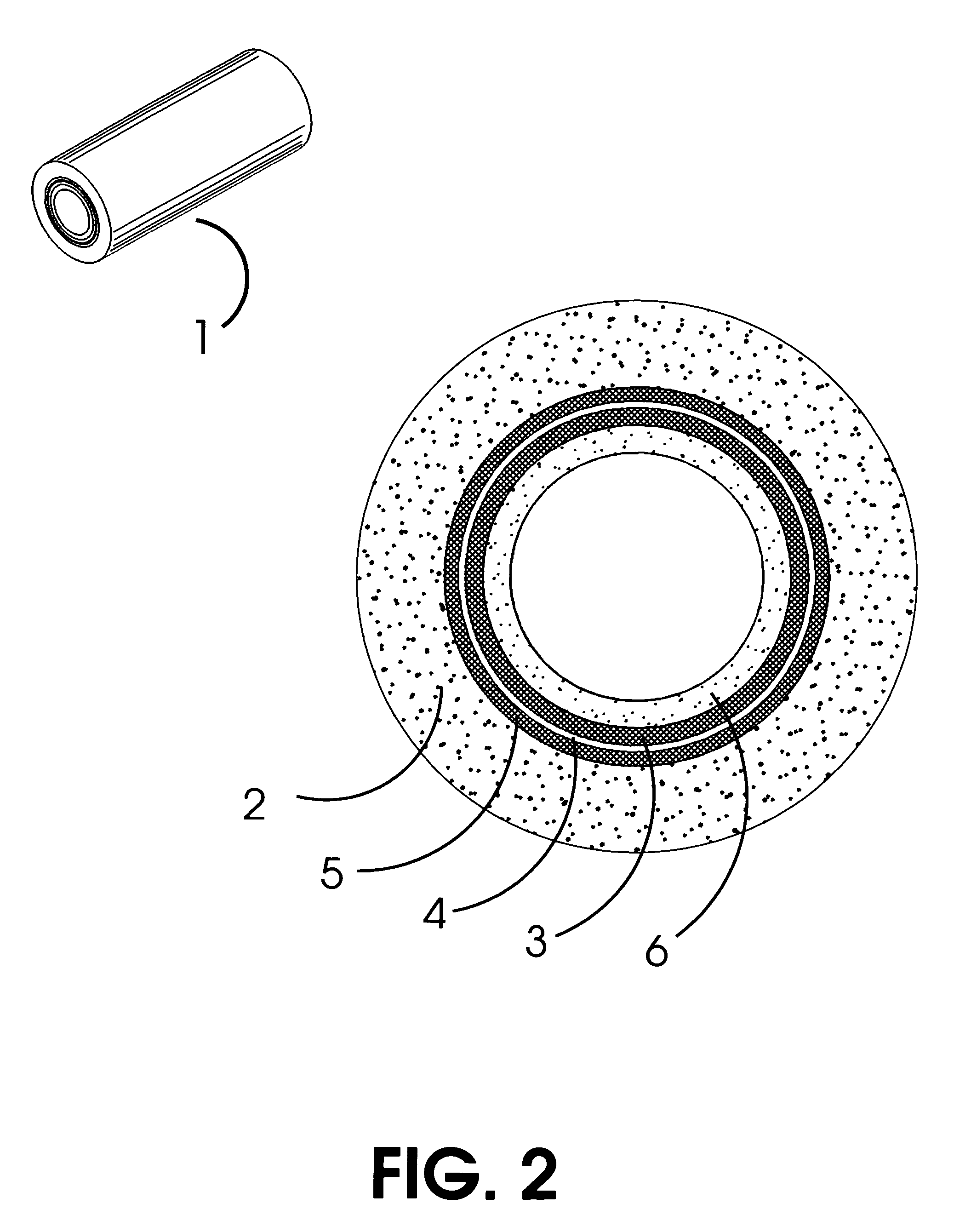
[0045]The present invention can best be described with reference to the attached drawings. The reference characters refer to the same parts throughout the various views. The drawings are not to scale and are presented to help illustrate the principles of the present invention in a clear manner. Further, the invention is drawn to a solid state electrochemical device comprising in one embodiment a solid oxide fuel cell (SOFC) which may operate in a power mode providing a source of useful electrical power to an external circuit and in another mode as a solid oxide electrolyzer cell (SOEC) which may operate by consuming electrical power and process heat while producing hydrogen.

[0046]As described above and with particular reference to FIG. 1, the solid state electrochemical device of the present invention is shown as a solid oxide fuel cell 1. The solid oxide fuel cell 1 may be comprised of a first porous, sintered support tube 2 having successive layers of a first porous electrode 3, a...


PUM

PropertyMeasurementUnit
wall thicknessaaaaaaaaaa
diameteraaaaaaaaaa
thicknessaaaaaaaaaa

Abstract

A low cost, robust bi-tubular solid state electrochemical device including a first porous, sintered support tube of a non-noble transition metal, a non-noble transition metal alloy and a cermet incorporating one or more of a non-noble transition metal and a non-noble transition metal alloy and having successive layers of a first porous electrode, a dense electrolyte and a second porous electrode, said successive layers disposed radially on the interior surface of said first porous, sintered support tube or disposed radially on the exterior surface of the first porous, sintered support tube and a second porous, sintered tubular member of a non-noble transition metal, a non-noble transition metal alloy and a cermet incorporating one or more of a non-noble transition metal and a non-noble transition metal alloy formed, deposited, or placed in electrical contact with the second porous electrode. The bi-tubular device of the present invention may comprise a solid oxide fuel cell or a solid oxide electrolyzer cell.

Description

CROSS REFERENCE TO RELATED APPLICATIONS[0001]This application claims priority from U.S. Provisional Application Ser. No. 60 / 923,590, entitled “Porous Bi-Tubular Solid State Electrochemical Device,” filed Apr. 16, 2007, the contents of which are hereby incorporated by reference in their entirety.FIELD OF THE INVENTION[0002]The present invention relates to solid state electrochemical devices and more particularly to porous tubular metal-supported solid oxide fuel cells and fuel stacks made there from. The present invention also relates to porous tubular metal-supported solid oxide electrolyzer cells.BACKGROUND OF INVENTION[0003]A fuel cell is a solid state electrochemical device that converts the chemical energy in fuels (such as hydrogen, methane, butane, or even gasoline and diesel) into electrical energy by exploiting the natural tendency of oxygen and hydrogen to react. By controlling the means by which such a reaction occurs and directing the reaction through a device, it is poss...

Claims


Application Information

Patent Timeline
Patent Type & Authority Applications(United States)
IPC IPC(8): H01M8/10C25B9/06C25B9/17
CPCC02F2201/003C25B9/06H01M8/243H01M8/1213H01M8/1226H01M8/0252Y02E60/50C25B9/17
Inventor TORGERSON, PAUL T.DUNSTAN, RICHARDWILLIAMS, MARK C.
Owner RGT UNIV OF CALIFORNIA
Learn More