Methods of forming activated carbons

a technology of activated carbons and carbon nanotubes, which is applied in the field of activated carbons, can solve the problems of high cost, marginal or unacceptable performance of current technology, and each approach has significant limitations, and achieves improved control of nanoparticle catalyzed, high energy density, and high energy density

Inactive Publication Date: 2008-10-16
UNIV OF KENTUCKY RES FOUND +1
View PDF43 Cites 30 Cited by
  • Summary
  • Abstract
  • Description
  • Claims
  • Application Information

AI Technical Summary

Benefits of technology

[0021]In order to address these issues, there is a need for a way to prepare activated carbons with a high energy density. There is also a need for precursor materials that will yield activated carbons with a high energy density. There is a further need for improved control of nanoparticle catalyzed mesopore formation in carbons.

Problems solved by technology

Much research has been devoted to this area, but for many practical applications such as hybrid electric vehicles, fuel cell powered vehicles, and electricity microgrids, the current technology is marginal or unacceptable in performance and too high in cost.
Each of these approaches has significant limitations.
Two of three notable exceptions suffer from methodological flaws.
This is readily proven not true.
Moreover, certain results Shi derived using this assumption he himself could not fully explain.
Extrapolations therefrom can be problematic.
Therefore, comparative BET external surface estimates are suspect.
But the disappointing result with working two-electrode EDLC devices, given in Table 2 and in FIG. 7 of the Tartu Paper, was that no significant improvement in carbon specific capacitance over RP-20 alone was seen.
Another previous effort (also focused on mesoporosity rather than rugosity) that combined chemical and physical activation together in one step did not produce a better material.
Both papers also found an unusual and disappointing result that capacitance actually decreased with increasing CO2 time despite substantial increases in total BET surface and mesoporosity.
Both papers go on to discuss the potential usefulness of longer duration simultaneous CO2 activation in partial removal of these supposed surface functional groups, since they may increase resistivity and may result in undesirably high self-discharge.
In certain critical filtration applications, for example pharmaceuticals, carbon impurities may undesirably leach into the filtrate.
It is conventionally thought that residual metal ion impurities may undesirably introduce faradic electrochemical redox shuttles, thereby increasing self-discharge and reducing stored charge over time.

Method used


Image

  • Methods of forming activated carbons
  • Methods of forming activated carbons
  • Methods of forming activated carbons

Examples


example 1

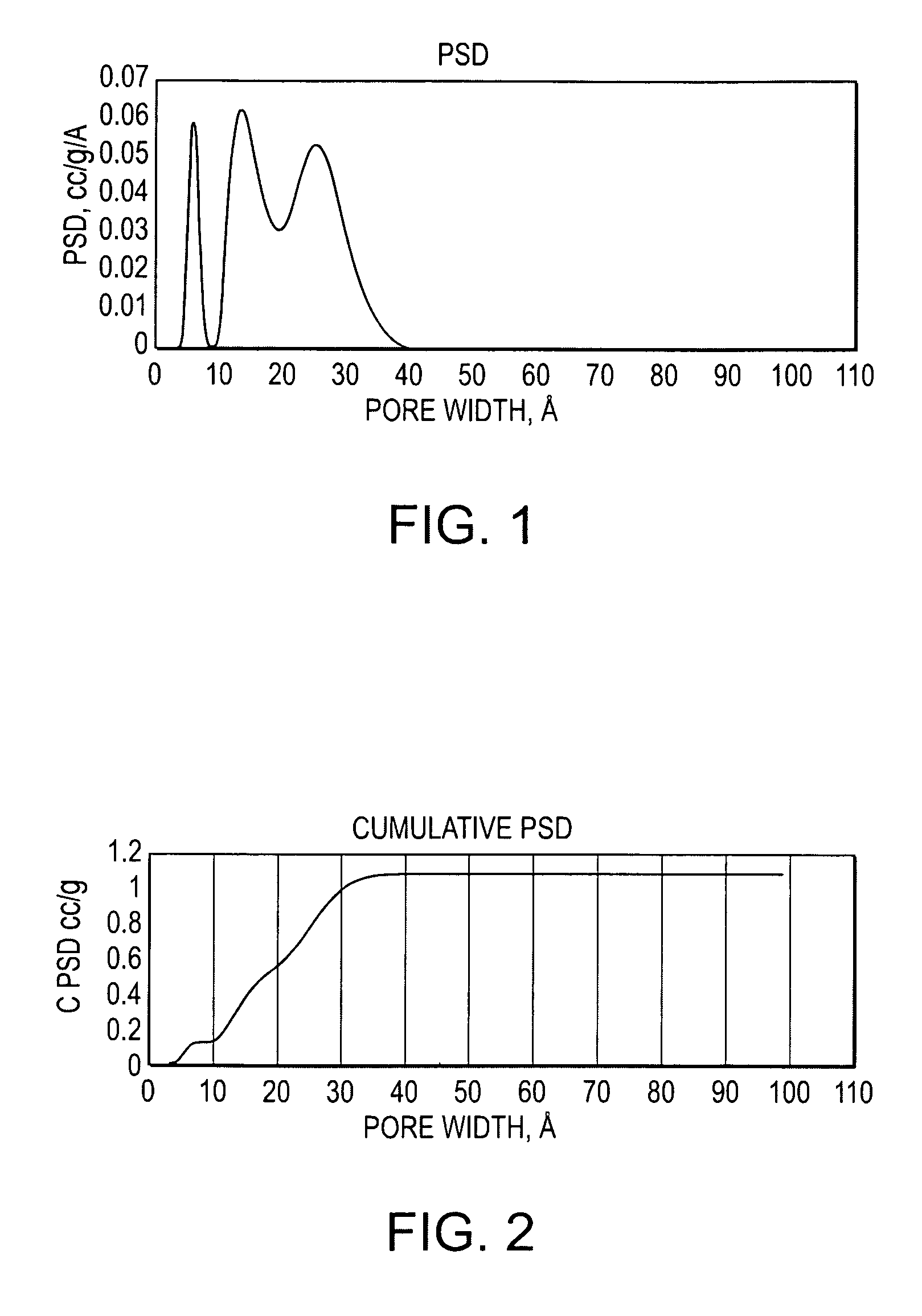
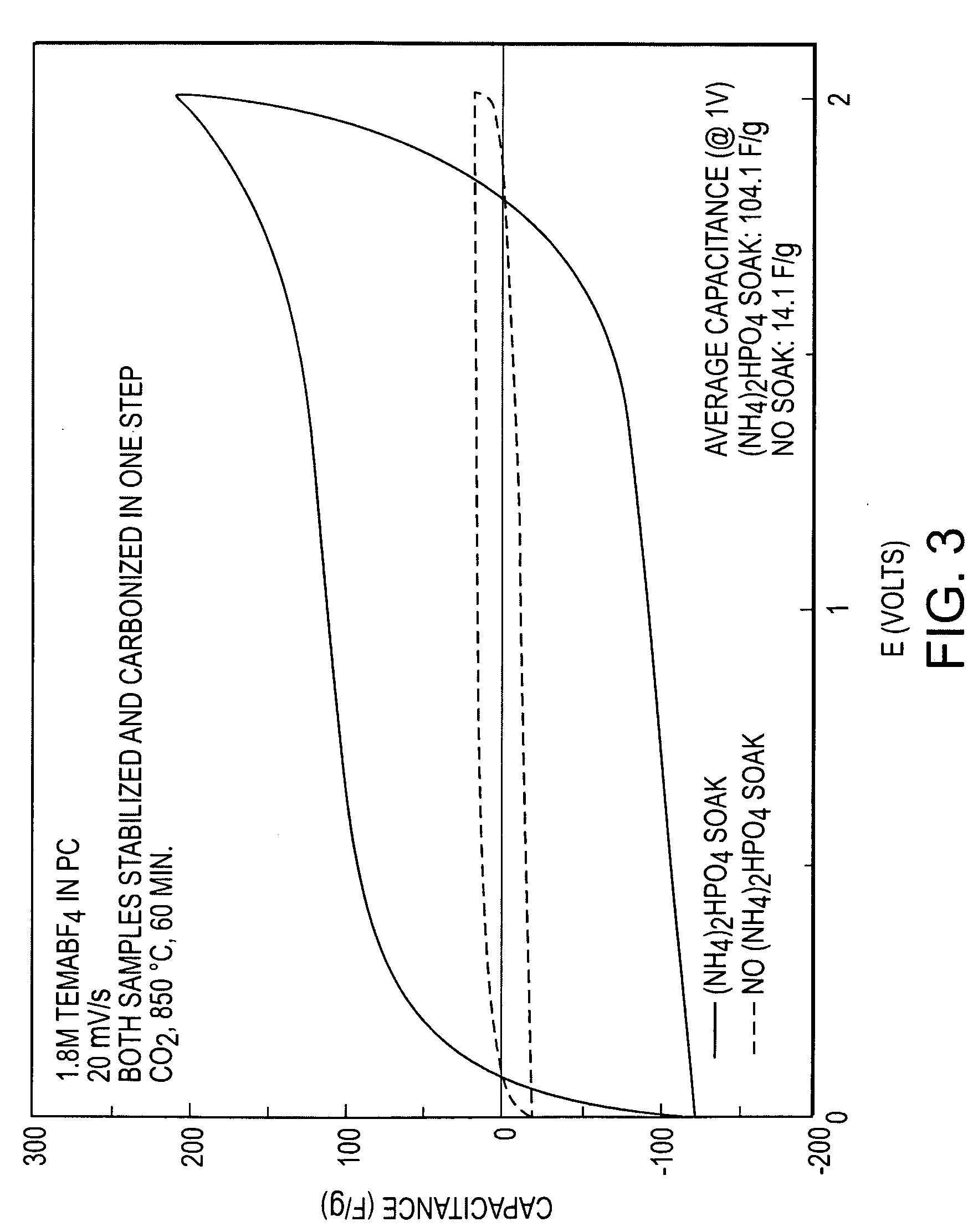
[0070]The Rayon of Comparative Example 1 was submerged in a 5% aqueous solution of diammonium phosphate ((NH4)2HPO4, hereinafter DAP, a common phosphorous derivative used as a plant fertilizer and fire retardant) for 30 minutes. The DAP coated Rayon was then oven dried. The DAP coated Rayon was carbonized / activated for 60 minutes under N2 at 850° C. and then compound activated by adding 200 mL / min CO2 at 850° C. for 60 minutes. The activated carbon mass loss was 83.7%, the BET surface was 2452 m2 / g, the TPV was 1.12943 cc / g, and the micropore proportion was only 44.8%. The material was 55.4% mesoporous.

[0071]This is less mass loss than Comparative Example 1, yet much higher surface area (over double), TPV (over double), and desirable mesopore volume and surface (over double). The material also has much more total surface than Comparative Example 2, which utilized carbon dioxide alone, and importantly with a majority of desirable mesopores, as shown by pore size distribution and cumu...

example 2

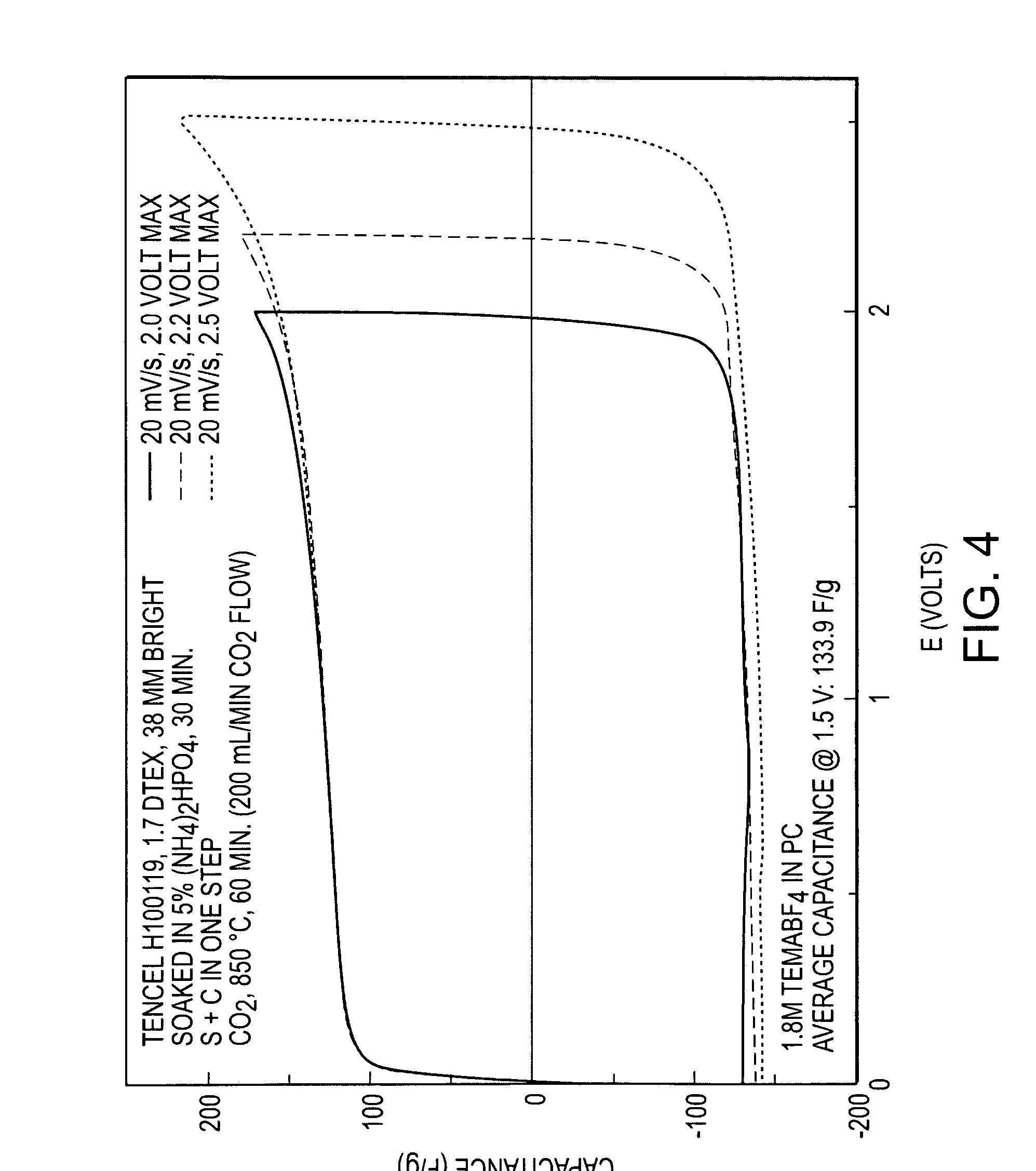
[0075]A Tencel® rayon fiber from Lenzing AG with a preferable smaller average diameter of 12 microns (Tencel H100119, dtex 1.7) was compound activated according to the method of Example 1 to produce an electrocarbon. The mass loss from green fiber was 63.7%, the BET surface was 2134 square meters / gram, the total pore volume was 0.85082 cc / g, and the mesopore proportion was 19.3%. The material's specific capacitance in working devices with 1.8 molar TEMA / PC electrolyte was 133.9 F / g at one volt of charge, with a near ideal CV as shown in FIG. 4. Results of Comparative Example 2 and Example 2 are summarized in Table 2 below.

TABLE 2ComparativeExample 2Example 2BET760m2 / g2134m2 / gTotal Pore0.3269cc / g0.85082cc / gVolumeCapacitance14.1F / g133.9F / g

[0076]Constant current charge discharge tests were run for devices made with the material of Example 2 at high current densities of up to 5 A / g. The results of these tests are shown in FIG. 5. The tests demonstrate to one of skill in the art that tru...

example 3

[0078]Tencel rayon fiber dtex 1.7 as in Example 2 was compound activated as in Examples 1 and 2. However, the activation time with carbon dioxide was increased to 75 minutes at 850° C. The mass loss from the green fiber was 71.3% (more than in Example 2 due to the longer activation time), the resulting BET surface was 2307 square meters per gram (only 8% more than Example 2), the total pore volume was 1.07 cc / g (desirably 25% more than Example 2), and the mesopore proportion was 45% (desirably 25.7% more than Example 2). Specific capacitance of the resulting material was 160.1 F / g measured at 20 mV / s at 1.5 volts of charge, and 156.5 F / g at 1.0 volts of charge. Linear constant current charge discharge curves to 2.5 amperes / g indicate true double layer capacitance, and impedance spectroscopy showed a surprising small region of Warburg impedance on the Nyquist plot, indicating excellent mass transport and very high power density despite the very high energy density.

[0079]While many ca...


PUM

PropertyMeasurementUnit
sizeaaaaaaaaaa
sizeaaaaaaaaaa
pore sizeaaaaaaaaaa

Abstract

Enhanced methods for preparing activated carbons have been discovered. In order to form an activated carbon, a carbon precursor material is coated with a phosphorus based chemical solution and physically activated. An activated carbon may also be formed by coating a green carbon precursor with a chemical solution that chemically reacts with carbon, carbonizing the resulting material, and physically activating the material during at least a portion of the carbonizing step. An activated carbon may also be formed by milling a carbon material to a predetermined particle size, then activating the milled particles. In another enhancement, an activated carbon is formed by coating a carbon or carbon precursor with nanoparticles, carbonizing if the carbon is a carbon precursor, then catalytically activating in air and an inert gas, and physically activating in steam or carbon dioxide. An activated carbon may also be formed by physically activating a previously chemically activated carbon.

Description

RELATED APPLICATIONS[0001]This application claims the benefit of U.S. Provisional Application No. 60 / 901,850, filed on Feb. 14, 2007, titled “Mesoporous Multiply Activated Carbon,” U.S. Provisional Application No. 60 / 961,432, filed on Jul. 20, 2007, titled “Processed Activated Carbons,” U.S. Provisional Application No. 60 / 961,320, filed on Jul. 20, 2007, titled “Sequentially Activated Carbons,” and U.S. Provisional Application No. 61 / 005,587 filed on Dec. 6, 2007, titled “Compound Activated Carbons.”TECHNICAL FIELD[0002]The present invention relates to activated carbons and to methods for their preparation. The activated carbons may be used in all manner of devices that may contain activated carbon materials, including but not limited to various electrochemical devices (e.g., capacitors, batteries, fuel cells, and the like), hydrogen storage devices, filtration devices, catalytic substrates, and the like.BACKGROUND OF THE INVENTION[0003]In many emerging technologies, such as electri...

Claims


Application Information

Patent Timeline
Patent Type & Authority Applications(United States)
IPC IPC(8): B01J37/02B01J21/18C01B32/336
CPCC01B31/10H01G9/058H01G11/34H01M4/583Y02E60/324H01M8/0234H01M12/005Y02E60/50Y02E60/13H01M4/96C01B32/336Y02E60/10H01G11/22C01B32/30B01J20/20H01G9/042B82Y30/00Y02E60/32
Inventor ISTVAN, RUDYARD LYLELIPKA, STEPHEN M.SWARTZ, CHRISTOPHER RAY
Owner UNIV OF KENTUCKY RES FOUND
Why Eureka
Try Eureka