Gelation controlled fluid flow in a microscale device

a microfluidic device and gelation control technology, applied in the field of microfluidic devices, can solve the problems of high reagent consumption, unsustainable, and many drugs failing clinical trials, and achieve the effects of low reagent consumption, improved tissue layer approximation, and high throughput screening application

Inactive Publication Date: 2008-10-16
HAYES STEVEN A +1
View PDF0 Cites 4 Cited by
  • Summary
  • Abstract
  • Description
  • Claims
  • Application Information

AI Technical Summary

Benefits of technology

[0032]Other advantages of some of the embodiments of the present invention include low reagent consumption, distinct interface betwee...

Problems solved by technology

Further, many drugs fail in clinical trials after hundreds of millions of dollars have already been invested.
This situation is obviously costly and undesirable, an possibly unsustainable, and pharmaceutical companies are constantly in need of technologies that improve their R&D capabilities.
A major challenge is using living cells to model human disease in the highly miniaturized and automated format used for high throughput screening (HTS), a widely used process for winnowing drug candidates from large chemical libraries early in drug development, cellular assays being a component of such HTS.
Unfortunately, the use of multiwell plates for cellular assays is imposing limits on their miniaturization and automation, and on the ability to reconstruct the microenvironment that cells inhabit in the body.
The miniaturization and automation issues are already recognized as significant technical hurdles hampering the use of cellular assays for HTS, and the microenvironment issue is emerging as the relationship between cellular context and function becomes better defined for cancer and other diseases.
Nanoliter liquid dispensing equipment is very complex and requires a major capital investment.
Moreover, even with the best equipment, the well to well variability in dispensed volumes is significant.
For this reason, and others explained below, the vast majority of cellular assays are done in 96 or 384 well plates, and further miniaturization is viewed as impractical.
The inability to miniaturize sufficiently means that some very useful types of cells with tremendous potential as disease models, ...

Method used


Image

  • Gelation controlled fluid flow in a microscale device
  • Gelation controlled fluid flow in a microscale device
  • Gelation controlled fluid flow in a microscale device

Examples


Embodiment Construction

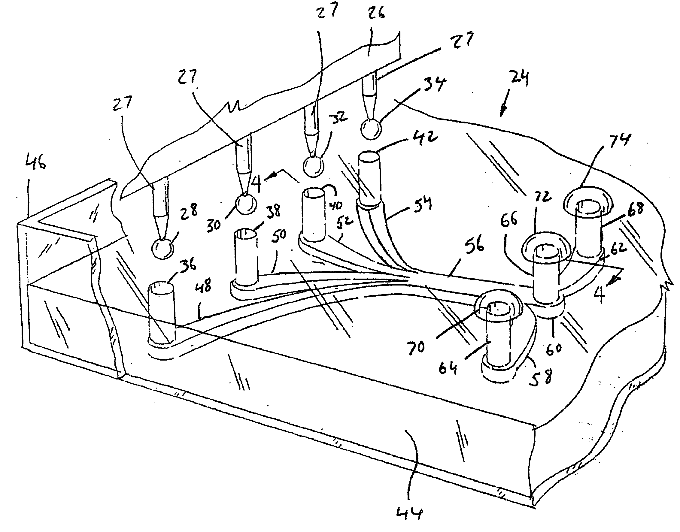
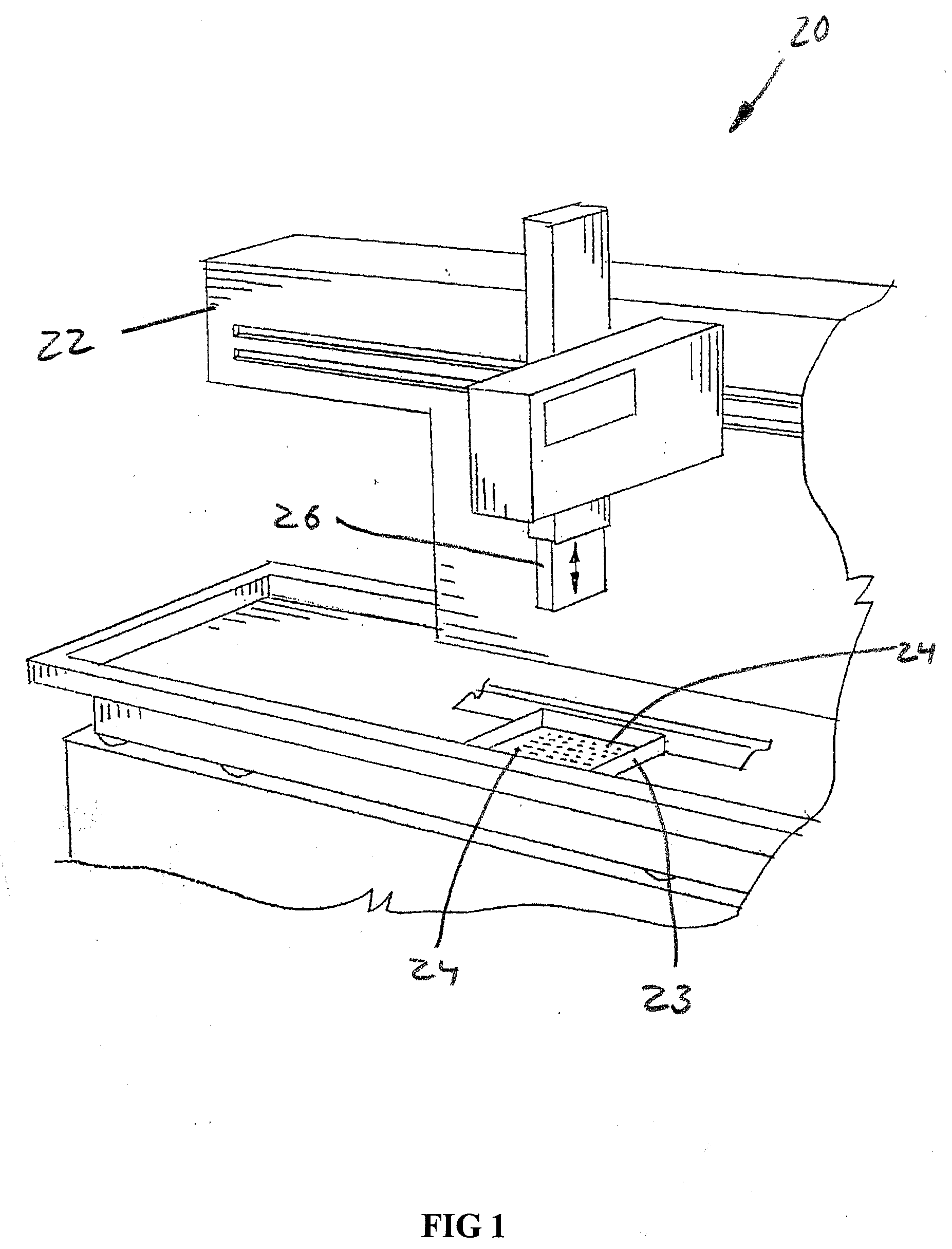
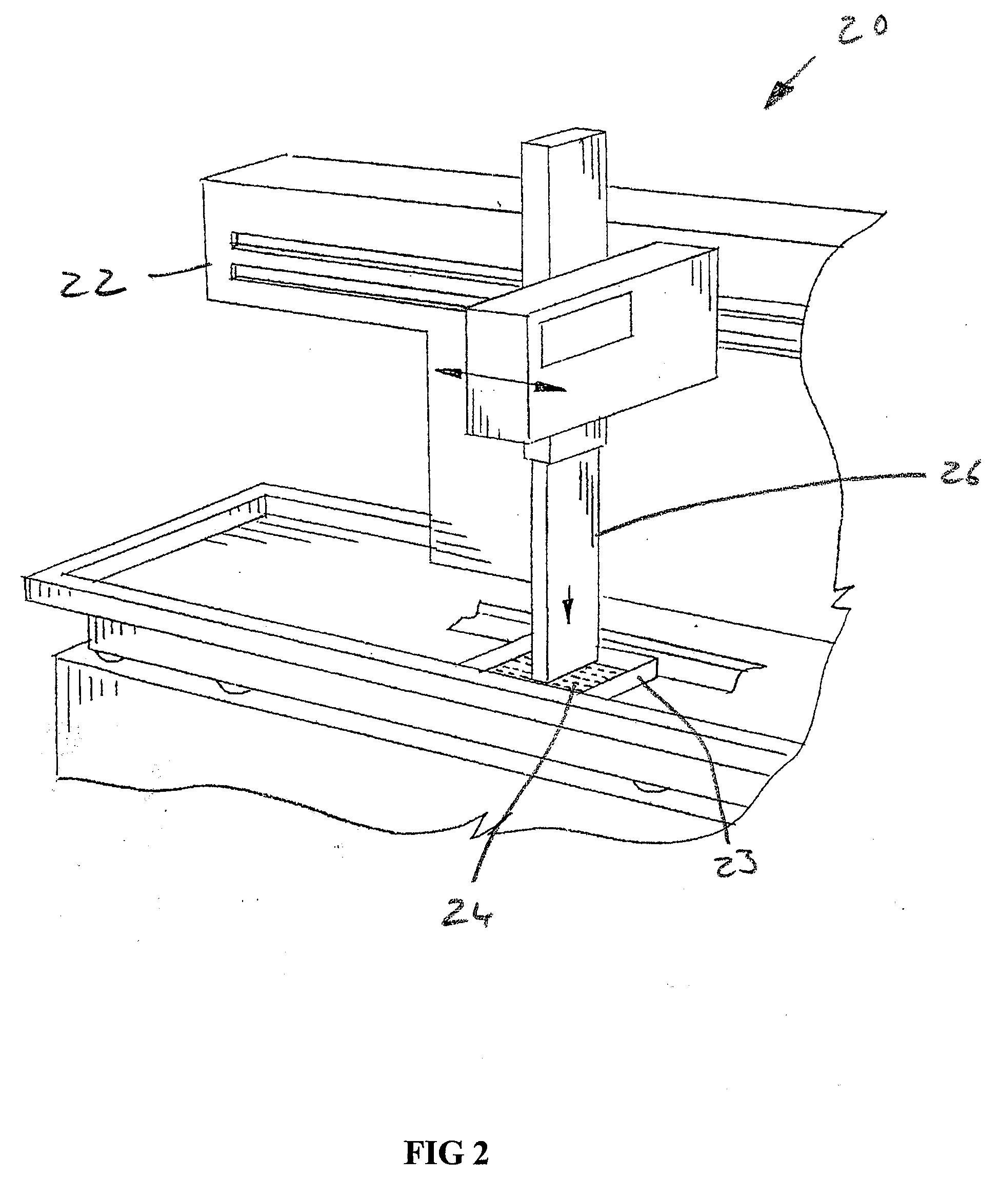
[0057]Referring now to the drawings, and more particularly to FIGS. 1 and 2, there is shown an automated high throughput screening system 20 which generally includes a multichannel pipettor 22, and a multiconduit array (MCA) 23 of mircrofluidic devices 24 according to the present invention, with the multichannel pipettor 22 in an up position. Multichannel pipettor 22 can be as manufactured by Beckman Coulter, or be one of many other multichannel pipettors. FIG. 2 illustrates the head 26 of multichannel pipettor 22 in a down position where individual pipettes 27 can deposit input droplets 28, 30, 32 and 34 (FIG. 3) into corresponding channel inlets 36, 38, 40 and 42 of one of the microfluidic devices 24 of multiconduit array 23.

[0058]More particularly, MCA 23 according to the present invention can be fabricated as a thin layer 44 of polydimethylsilane, a biologically inert elastomeric polymer, and with a tray 46 of clear plastic (polystyrene), or other materials. In one embodiment, a...


PUM


Abstract

A method of self regulating a process of manufacturing a biological device which includes the steps of: choosing a first material and a second material based on a correlation of a parameter of the second material with a parameter of the first material; and merging the first material with the second material where the correlation of the parameter of the second material with the parameter of the first material self regulates the merging step to provide a distinct patterning of the first material and the second material.

Description

CROSS-REFERENCE TO RELATED APPLICATIONS[0001]This application claims the benefit of U.S. Provisional Application No. 60 / 923,606 filed Apr. 16, 2007 which is incorporated herein by reference in its entirety.FIELD OF THE INVENTION[0002]The present invention relates to microscale devices and methods of use thereof, and, more particularly, to gelation controlled fluid flow in a microfluidic device and devices and methods derived therefrom.BACKGROUND OF THE INVENTION[0003]It is not unusual for a new drug to take ten to twelve years to bring to market at a cost in the high hundreds of millions of dollars, and with an overall success rate is less than 20%. Further, many drugs fail in clinical trials after hundreds of millions of dollars have already been invested. This situation is obviously costly and undesirable, an possibly unsustainable, and pharmaceutical companies are constantly in need of technologies that improve their R&D capabilities. A major challenge is using living cells to mo...

Claims


Application Information

Patent Timeline
IPC IPC(8): C40B60/12C40B60/00B05D5/00
CPCB01L3/5023B01L3/50273B01L3/502776B01L2300/069B01L2300/0816B01L2400/0406B01L2400/0457B01L2400/0487
Inventor HAYES, STEVEN A.MEYVANTSSON, IVAR
Owner HAYES STEVEN A
Why Eureka
Try Eureka