Internal combustion engine and combustion method of the same

a combustion engine and combustion method technology, applied in the direction of machines/engines, combustion-air/fuel-air treatment, electric control, etc., can solve the problems that the combustion mode cannot solve the essential task of premixed compressed combustion and the possibility of unstable combustion, and achieve the effect of strong turbulent flow

Inactive Publication Date: 2008-10-23
NISSAN MOTOR CO LTD
View PDF8 Cites 24 Cited by
  • Summary
  • Abstract
  • Description
  • Claims
  • Application Information

AI Technical Summary

Benefits of technology

[0011]According to the internal combustion engine of the invention, the flame, produced by combustion of the fuel gas, tends to enlarge along a spray of fuel gas, and thus it is possible to multipoint-ignite a premixed mixture at a plurality of points in a combustion chamber....

Problems solved by technology

However, when combusting a lean mixture by spark-ignition, there is a possibility of unstable combustion.
Fundamentally, such a combustion mode cannot solve the es...

Method used


Image

  • Internal combustion engine and combustion method of the same
  • Internal combustion engine and combustion method of the same
  • Internal combustion engine and combustion method of the same

Examples


first embodiment

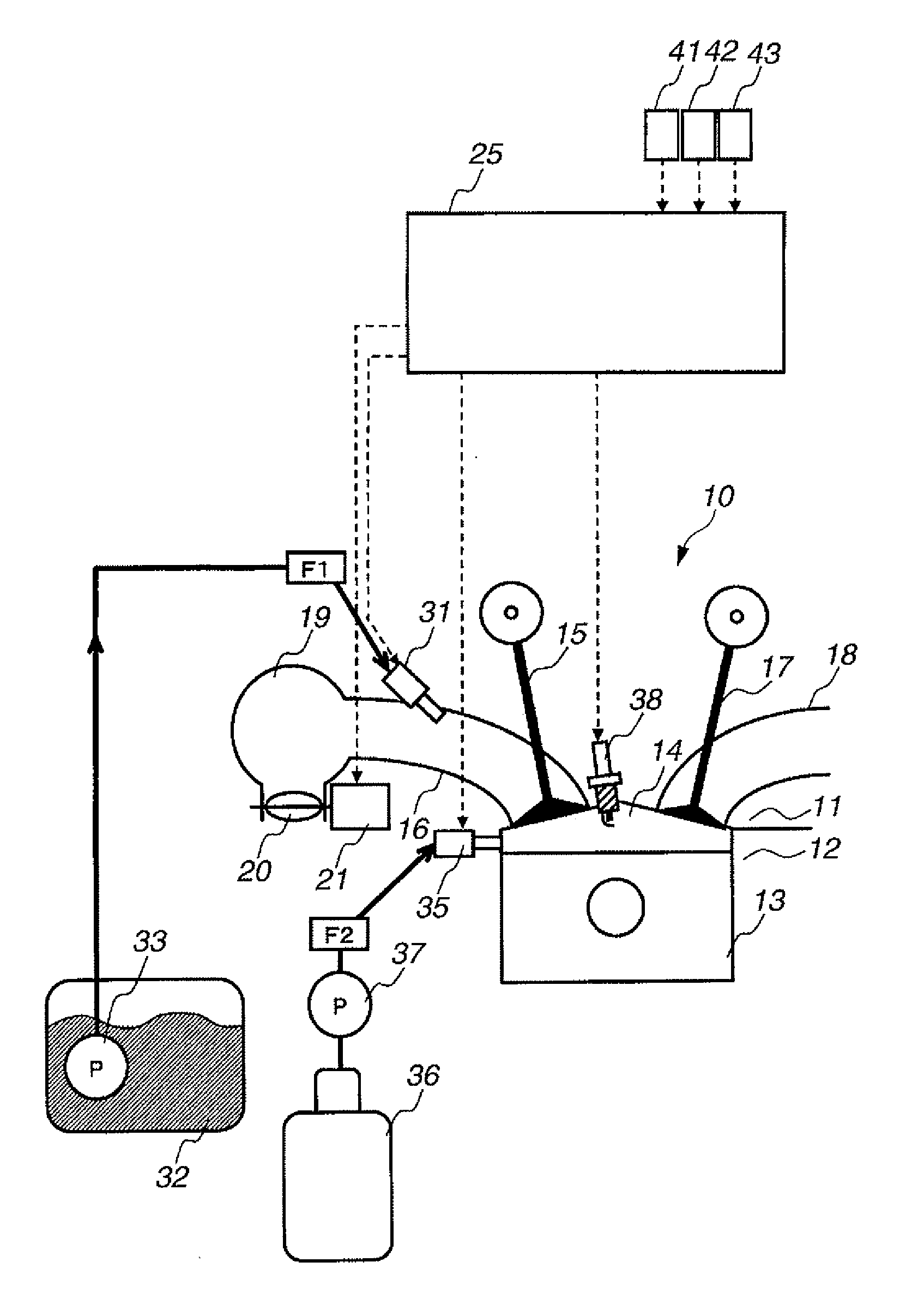
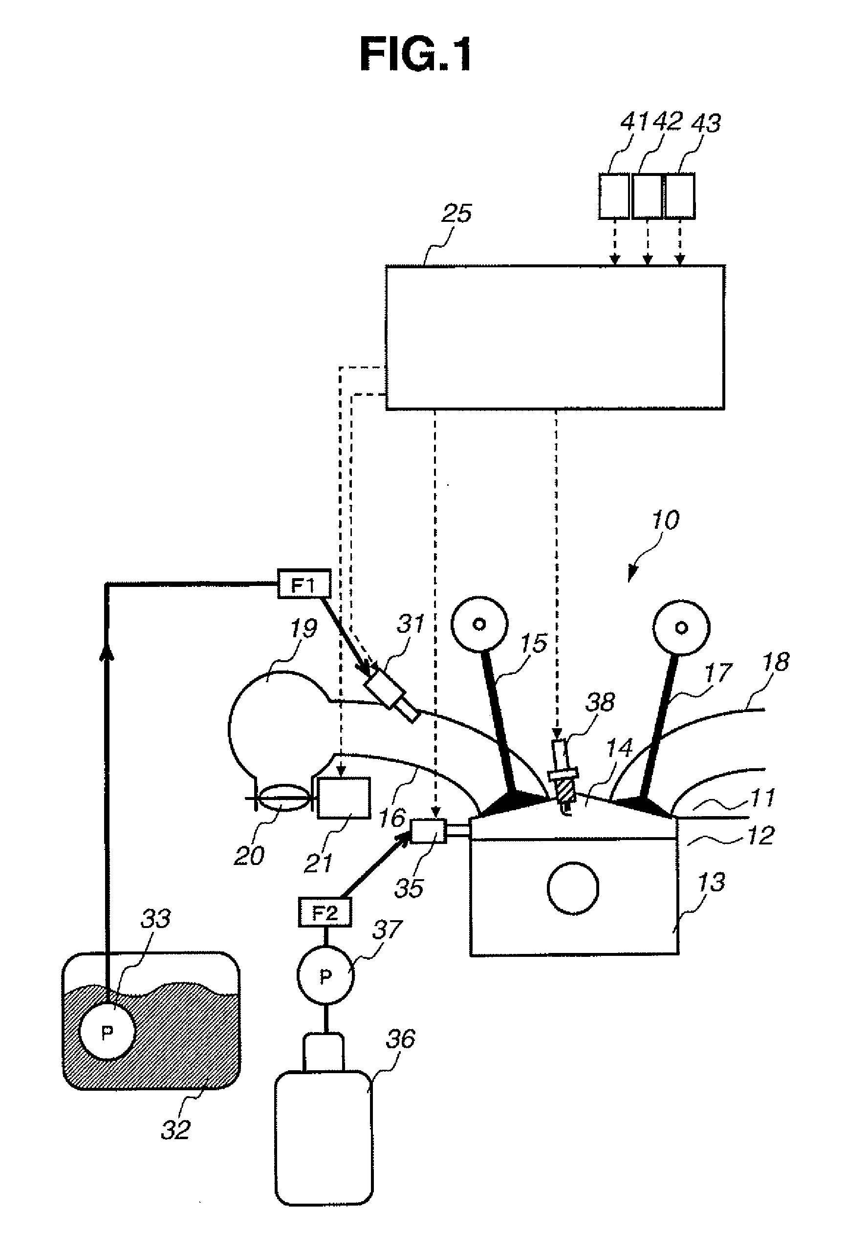
[0026]FIG. 1 shows the system diagram of an engine (an internal combustion engine) of the invention. An engine 10 is formed with a combustion chamber 14, which is defined by a cylinder head 11, a cylinder block 12, and a piston 13.

[0027]Combustion chamber 14 is formed, so that intake air is introduced through an intake valve 15 via an intake port 16, serving as an intake-air passage, into the combustion chamber. Additionally, the combustion chamber is formed, so that exhaust gas is exhausted from the combustion chamber through an exhaust valve 17 into an exhaust port 18, serving as an exhaust-gas passage. A manifold section (an intake manifold) 19 is provided in a middle of the intake-air passage. A throttle valve 20 is further provided in the intake-air passage and located upstream of manifold section 19. The actuating shaft of throttle valve 20 is fixedly connected to an output shaft of a step motor 21. The output shaft of step motor 21 is rotated responsively to a command signal ...

second embodiment

[0052]In the second embodiment, part of normal paraffin, separated by fuel separator 61, may be converted to produce hydrogen (fuel gas F5) by way of partial oxidation (reforming reaction) utilizing a rhodium system catalyst, within fuel reformer 63. As an example of such a reaction, when fuel-reforming normal heptane (C7H16) by way of partial oxidation by fuel reformer 63, the chemical reaction is represented by the following reaction formula.

C7H16 (normal heptane)+3.5O2→7CO+8H2 wherein the partial oxidation is an exothermic reaction.

[0053]Hydrogen (fuel gas F5), produced by fuel reformer 63, is supplied via fuel gas pump 65 to gas injection valve 35. As the hydrocarbon fuel F4 having a high self-ignitability, part of normal paraffin, which is not subjected to the reforming reaction within fuel reformer 63, is supplied via fuel pump 64 to the second fuel injection valve 51b.

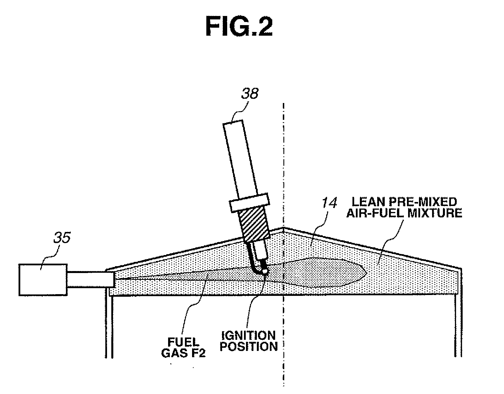
[0054]FIG. 5 is the cross section showing the detailed form of combustion of the lean premixed mixture in th...

third embodiment

[0080]As seen in FIG. 9, a first gas injection valve 55a and a second gas injection valve 55b, both serving as the fuel gas supply device, are located at the center of the top face of combustion chamber 14. The first gas injection valve 55a has a single nozzle, for injecting fuel gas F5 toward the center of the piston crown of a reciprocating piston 13. Piston 13 has a recessed cavity 13b (a small bowl) formed in the center section of the piston crown. On the other hand, the second gas injection valve 55b is configured to inject fuel gas F5 radially into combustion chamber 14. In the third embodiment, fuel gas F5 is supplied to each of the first and second gas injection valves 55a-55b via fuel reformer 63 by fuel pump 65. Fuel-supply control for the first gas injection valve 55a and fuel-supply control for the second injection valve 55b can be made independently of each other by the fuel supply control device, incorporated in ECU 25.

[0081]FIG. 10 is the cross section showing the det...


PUM


Abstract

An internal combustion engine, including a premixed mixture formation device that forms a premixed mixture of fuel and air in a combustion chamber, a fuel gas supply device that injects fuel gas directly into the combustion chamber, and an ignition device that ignites the fuel gas. The fuel gas supply device is configured to inject the fuel gas into the premixed mixture near a top dead center of a compression stroke such that a spray of the fuel gas passes through a firing position of the ignition device, to produce the spray of the fuel gas in a predetermined area substantially extending from one end of a cylinder bore to the other end as viewed in a cylinder-bore direction defined by a centerline of the cylinder bore. The ignition device is configured to directly ignite the spray of the fuel gas and to ignite and burn the premixed mixture by way of flame propagation along the spray of the fuel gas.

Description

CROSS-REFERENCE TO RELATED APPLICATIONS[0001]This application claims priority under 35 U.S.C. § 119 to Japanese Patent Application No. 2007-111085, filed on Apr. 20, 2007, which is incorporated by reference herein in the entirety.BACKGROUND OF THE INVENTION[0002]1. Field of the Invention[0003]The present invention relates to an internal combustion engine, configured to burn a premixed air-fuel mixture formed in a combustion chamber by way of spark-ignition.[0004]2. Description of Related Art[0005]In conventional spark-ignition engines, it is generally known that a thermal efficiency can be enhanced and air pollutants contained in exhaust gases can be reduced by rarefying, or leaning, out a mixture of fuel and air. However, when combusting a lean mixture by spark-ignition, there is a possibility of unstable combustion. In order to suppress such unstable combustion, and also to enlarge a lean-combustion limit of a lean mixture or a lean misfire limit, there have been proposed and deve...

Claims


Application Information

Patent Timeline
IPC IPC(8): F02M43/00F02B5/00F02B3/02
CPCF01L2001/0537F02B17/005F02B23/101F02B23/105F02B2023/103F02B2075/125F02B2275/16F02D15/00F02D19/081F02D41/0025F02D41/0027F02D41/3047F02D41/3094F02M25/12F02M27/02Y02T10/125Y02T10/36Y02T10/123F02D19/0644F02D19/0671F02D19/0689F02D19/0692F02D19/024Y02T10/32Y02T10/12Y02T10/30
Inventor NODA, TORUARAKI, TAKASHIASHIDA, KOICHI
Owner NISSAN MOTOR CO LTD
Why Eureka
Try Eureka