

Miniature quantum well thermoelectric device
- Summary
- Abstract
- Description
- Claims
- Application Information
AI Technical Summary
Benefits of technology
Problems solved by technology
Method used
Image

Examples
Embodiment Construction
Applicants Earlier Patents
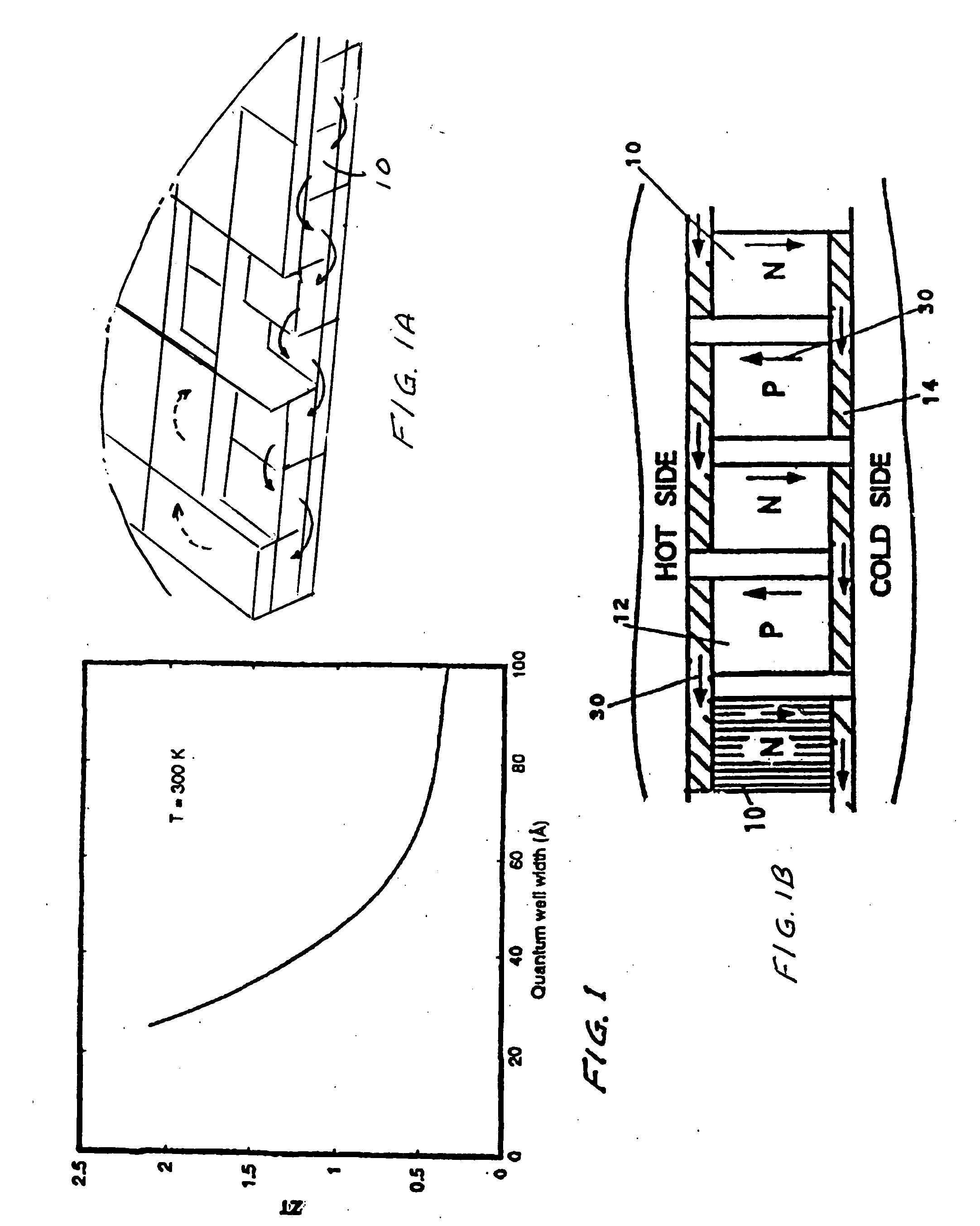
[0042]On Aug. 1, 2000 Applicants were granted U.S. Pat. Nos. 6,096,964 and 6,096,965 both of which have been incorporated herein by reference. In these patents Applicants disclose techniques for placing the thin alternating layers on film substrates to produce quantum well thermoelectric modules. In these patents the alternating layers specifically described include layers comprised of silicon and silicon-germanium. The silicon is referred to as barrier layers and the SiGe layers are referred to as conducting layers and are appropriately doped to produce n legs and p legs.
[0043]An n-doping atom is typically the atom having one more electron than the base semiconductor atoms. The extra atom provides a conducting electron supporting current flow. A p-doping atom is typically the atom having one fewer electron than the base semiconductor atoms. The missing electron becomes an electron acceptor location (i.e., a hole) supporting current flow. As explained in th...
PUM
 Abstract
Description
Claims
Application Information