
Flue Gas Desulfurization Process Utilizing Hydrogen Peroxide

Active Publication Date: 2008-10-30
PEROXYCHEM LLC
View PDF8 Cites 7 Cited by
  • Summary
  • Abstract
  • Description
  • Claims
  • Application Information

AI Technical Summary

Benefits of technology

[0008]In accordance with the present invention, a SO2-containing flue gas stream is desulfurized in a flue gas desulfurization process which comprises (i) contacting a SO2-containing flue gas stream with a recirculating stream of an aqueous medium containing concentrated sulfuric acid and hydrogen peroxide, under conditions such that SO2 is absorbed from the flue gas into the aqueous medium to yield a desulfurized flue gas stream and such that the absorbed SO2 reacts with the hydrogen peroxide to produce additional sulfuric acid in the aqueous medium; (ii) diverting a portion of the recirculating aqueous sulfuric acid stream for recovery of the additional sulfuric acid as gypsum in a neutralization step, in which sufficient neutralizing agent selected from limestone, lime and calcium hydroxide is introduced into the diverted aqueous medium to neutralize the sulfuric acid present and produce a gypsum product; (iii) refortifying the recirculating aqueous sulfuric acid stream with concentrated hydrogen peroxide to maintain a steady state H2O2 concentration in the recirculating aqueous sulfuric acid stream introduced into contact with the SO2-containing flue gas stream; and (iv) adjusting the hydrogen peroxide concentration, the sulfuric acid concentration, and water balance in the recirculating aqueous sulfuric acid stream such that heat of reaction generated du

Problems solved by technology

Retrofitting existing older small capacity power plants with desulfurization equipment is often limited by the lack of available room, a significant issue with the installation of wet scrubbing desulfurization equipment.
Dry or semi-dry scrubbing methods may not be amenable in retrofit situations, since calcium sorbents can be detrimental to existing electrostatic precipitator performance, reaction kinetics between sulfur dioxide and calcium sorbents require long gas-solid residence times for complete reaction, or the desulfurization byproduct characteristics (e.g., solubility) may not permit inexpensive disposal in a landfill.
The desulfurization systems of Godara et al. produce sulfuric acid and / or calcium sulfate as byproducts but do not address the complexity of the unit operations required to recover gypsum (calcium sulfate dihydrate) as a byproduct.

Method used


Image

  • Flue Gas Desulfurization Process Utilizing Hydrogen Peroxide
  • Flue Gas Desulfurization Process Utilizing Hydrogen Peroxide

Examples


example 1

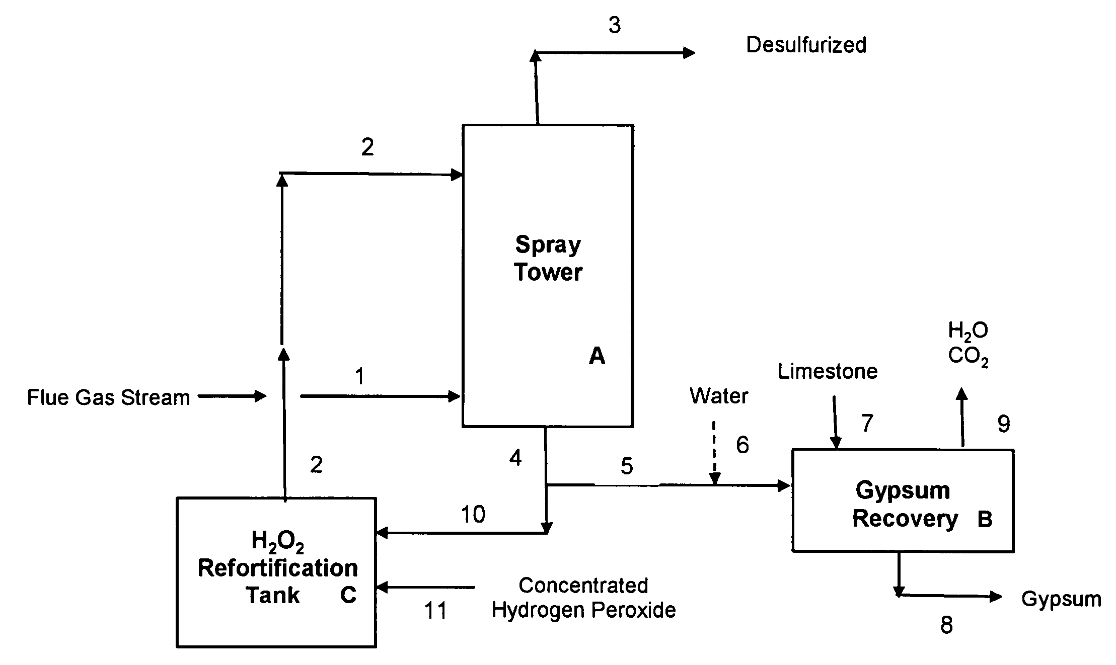
[0067]Example 1 illustrates a preferred embodiment of the present invention, using a concentrated sulfuric acid scrubber liquor stream also containing hydrogen peroxide, for desulfurization of a flue gas stream from a combustion boiler utilizing high sulfur coal. The desulfurization process of this Example 1 is operated in a manner that requires no input of external heat to the gypsum precipitation and recovery step. FIG. 1 illustrates a schematic flow diagram of this preferred embodiment; reference numerals and letters in the drawing are included in the process description which follows.

[0068]The flue gas composition in this Example 1 (and in subsequent Examples) is obtained from combustion of high sulfur coal containing 2.5 wt % sulfur, burned using 10% excess air. The flue gas composition is shown in Table 1.

TABLE 1Flue Gas CompositionComponentConcentration: Wt BasisConcentration: Volume BasisSO20.49wt %0.22vol %SO349ppmw18ppmvH2O5.6wt %9.0vol %CO222.7wt %15.0vol %Other Gases71.2...

example 2

[0079]Example 2 illustrates another preferred embodiment of the present invention, using a concentrated sulfuric acid scrubber liquor stream also containing hydrogen peroxide, for desulfurization of a flue gas stream from a combustion boiler utilizing high sulfur coal. The desulfurization process of this Example 2, like that of Example 1, is operated in a manner that requires no input of external heat to the gypsum precipitation and recovery step. In Example 2, the concentration of the make-up hydrogen peroxide 11 used to fortify the recirculating aqueous sulfuric acid stream 10 (see FIG. 1) is 36.7 wt % H2O2, as compared with 50 wt % H2O2 used in Example 1.

[0080]The flue gas stream used in Example 2 is identical to that of Example 1, but the recirculating aqueous sulfuric acid stream has a slightly different composition and flow rate. In the desulfurization step, the recirculating aqueous stream 2 is introduced into the spray tower A at a flow rate of 12,020 lb / hr and contains 49.9...

example 3

[0085]Example 3 illustrates yet another preferred embodiment of the present invention, using a concentrated sulfuric acid scrubber liquor stream also containing hydrogen peroxide, for desulfurization of a flue gas stream from a combustion boiler utilizing high sulfur coal. The desulfurization process of this Example 3, like that of Examples 1 & 2, is operated in a manner that requires no input of external heat to the gypsum precipitation and recovery step B, shown in FIG. 1. In Example 3, the concentration of the make-up hydrogen peroxide 11 used to fortify the recirculating aqueous sulfuric acid stream 10 (see FIG. 1) is again 36.7 wt % H2O2, as in Example 2.

[0086]The spray tower A in Example 3 is operated at a higher temperature than that assumed for Example 2, leading to higher water evaporation rates. In Example 2, no net water was evaporated during the desulfurization step in the spray tower A, i.e., the water vapor in the incoming flue gas stream 1 was identical to that presen...


PUM

PropertyMeasurementUnit
Fractionaaaaaaaaaa
Concentrationaaaaaaaaaa

Abstract

A flue gas desulfurization process in which a SO2-containing flue gas stream is contacted with a recirculating stream of an aqueous medium containing concentrated sulfuric acid and hydrogen peroxide, to yield a desulfurized flue gas stream and to produce additional sulfuric acid in the aqueous medium. A portion of the recirculating aqueous sulfuric acid stream is diverted for recovery of the additional sulfuric acid as gypsum in a neutralization step, and the process parameters are adjusted so that the heat of reaction generated during the neutralization step is sufficient to evaporate the free water that is present and yield a gypsum product that is substantially dry.

Description

CROSS REFERENCE TO RELATED APPLICATION[0001]This application claims the benefit of U.S. Provisional Application No. 60 / 926,877, filed Apr. 30, 2007.FIELD OF THE INVENTION[0002]The present invention relates to a flue gas desulfurization process for removal of SO2 from flue gas streams. More particularly, this invention relates to a SO2 flue gas desulfurization process that uses a recirculating aqueous gas scrubbing stream containing sulfuric acid and hydrogen peroxide, from which gypsum is recovered as a byproduct.BACKGROUND OF THE INVENTION[0003]Sulfur dioxide, SO2, and sulfur trioxide, SO3, collectively called SOx gases, are normally formed during the combustion of fuels such as coal, coke or oil that also contain sulfur. These SOx gases are considered air pollutants, and desulfurization measures are often required to control or minimize the amounts of these gases in the flue gas streams that are released into the atmosphere. Electric utility power plants are a significant source o...

Claims


Application Information

Patent Timeline
IPC IPC(8): B01D53/50B01D53/14
CPCB01D53/507B01D53/73B01D2251/106B01D2251/506C01B17/74C01F11/464Y02C20/40
Inventor PFEFFER, HENRY A.COPENHAFER, WILLIAM C.
Owner PEROXYCHEM LLC
Learn More