Process for the rapid fabrication of composite gas cylinders and related shapes

Active Publication Date: 2008-10-30
A&P TECH
View PDF33 Cites 21 Cited by
  • Summary
  • Abstract
  • Description
  • Claims
  • Application Information

AI Technical Summary

Benefits of technology

[0006]The invention utilizes a formed liner which is over-wrapped with a dry fiber fabric preform or braid. Tension control is incorporated through use of a tri-axial form of material such that tension can be developed in the preform without deformation. The wrapped liner is loaded into a mold cavity defining the outer shape of the part to be made. The loading operation incorporates rotation of the liner and fiber preform such that the tension on the preform is improved and is coordinated with tool closing to effectively eliminate any undesirable possibility of wrinkling of the preform.
[0007]The liner is connected to process controls capable of delivering heat and cooling as well as pressure to the inside of the liner via fluid systems. The capability to control the process from the internal liner side is used during the subsequent resin transfer molding operation. Resin is injected into the dry fiber preform occupying the cavity between mold wall and liner. The temperatures and pressures are capable of be

Problems solved by technology

The primary issues associated with implementation of fuel cell vehicles and the like are in manufacturing components at rates compatible with vehicle production, and at costs that can be borne by the consumer and industry.
Current high-pressure storage cylinders need to be carbon composite due to the weight penalty associated with metallic tanks.
In the above referenced state-of-the-art, from 12 to 24 different tools and process lines are necessary for the parallel processi

Method used


Image

  • Process for the rapid fabrication of composite gas cylinders and related shapes
  • Process for the rapid fabrication of composite gas cylinders and related shapes
  • Process for the rapid fabrication of composite gas cylinders and related shapes

Examples


Embodiment Construction

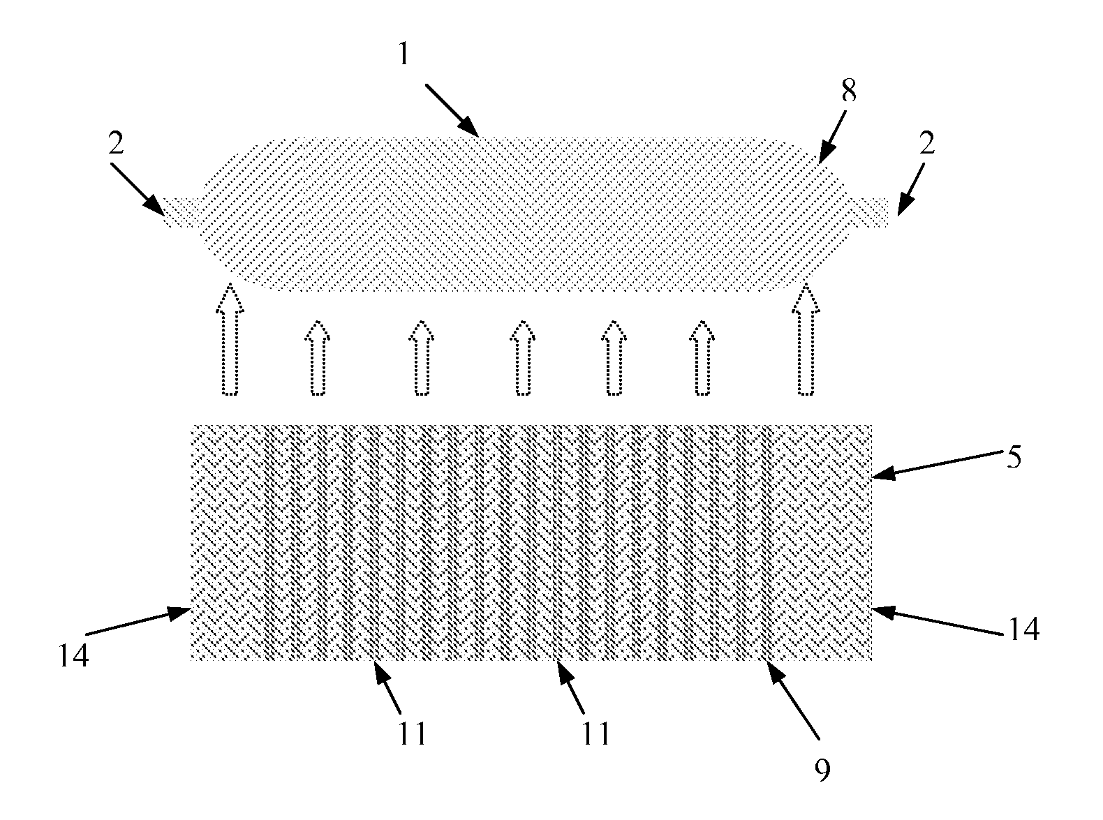
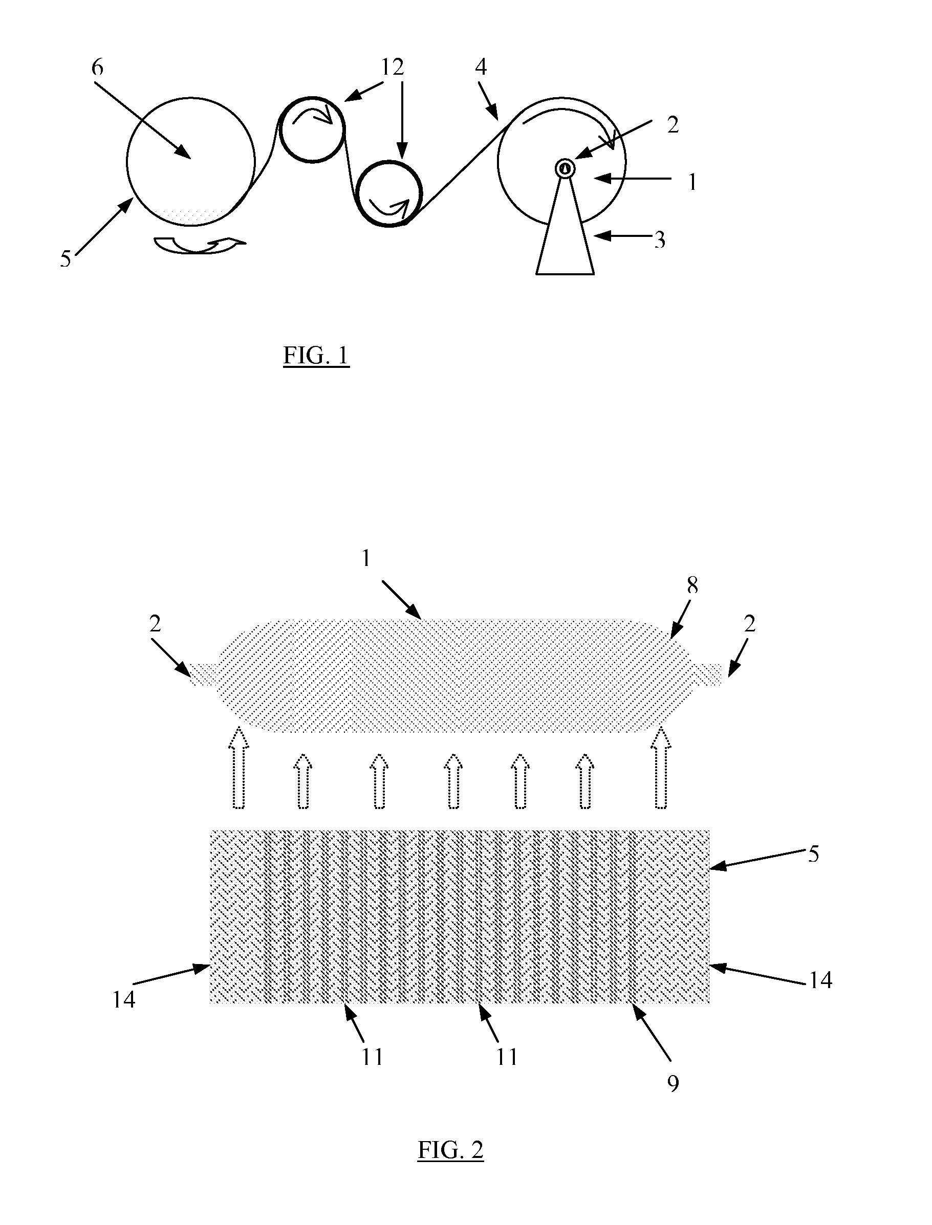
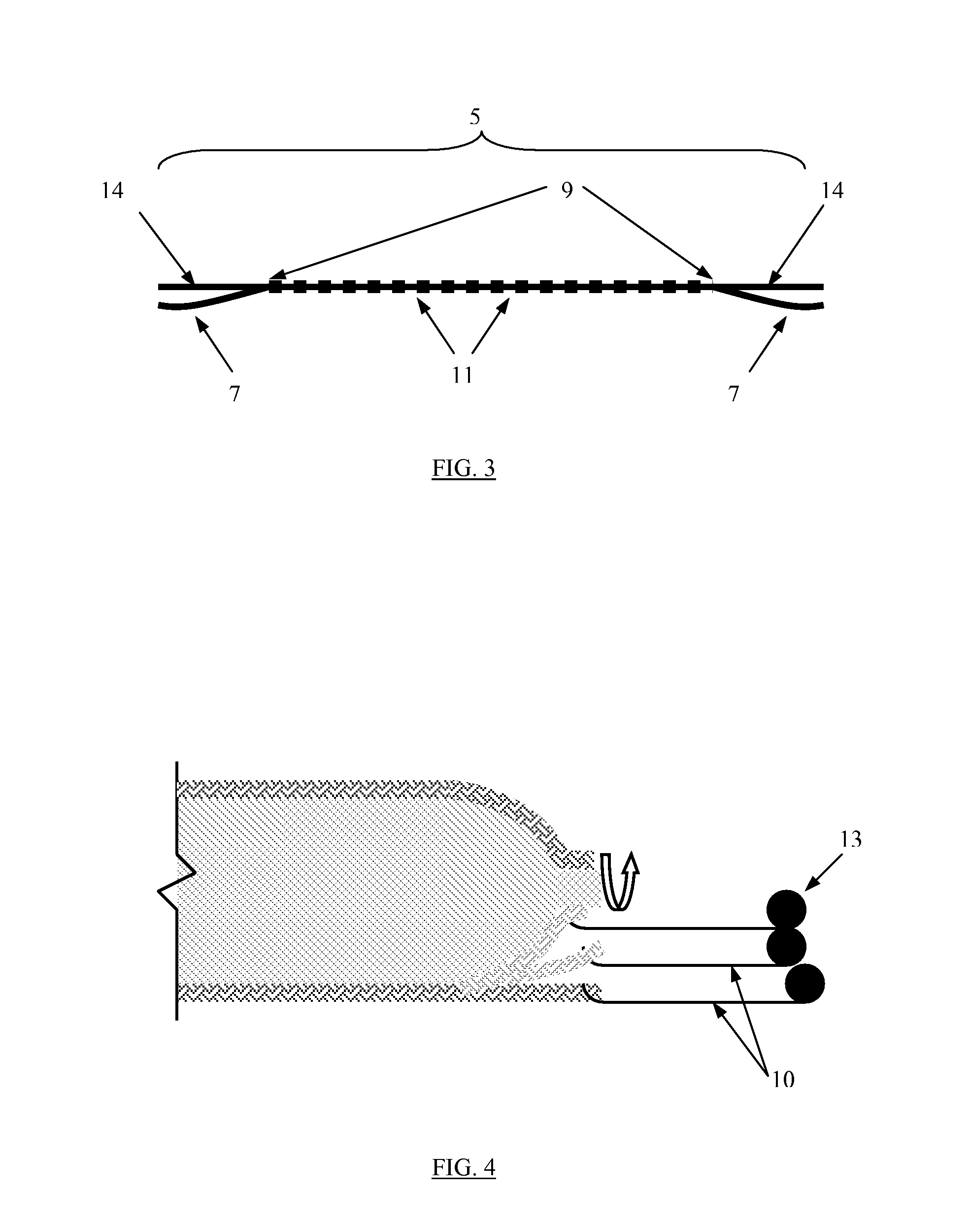
[0016]The following discussion of the embodiments of the invention directed to a rapid manufacturing process for a compressed hydrogen tank is merely exemplary in nature, and is in no way intended to limit the invention or its applications or uses. However, as will be appreciated by those skilled in the art, the process has application to produce tanks other than compressed hydrogen tanks and to produce structures with liners applicable in a number of fields utilizing composites as the preferred material.

[0017]An invention is developed which consists of several process steps, intricately linked, in which no single step is more than 10-20 minutes in total cycle time, thereby resulting in a part fully completed coming off each line every 10-20 minutes.

[0018]A cylinder liner 1 is formed through one of several options, using either superplastic forming of metal pipe with threaded ends, spin forming of cylinders from metal sheet or tubing, or plastic blow-molding or injection molding to ...


PUM

PropertyMeasurementUnit
Thicknessaaaaaaaaaa
Forceaaaaaaaaaa
Pressureaaaaaaaaaa

Abstract

A method of fabricating a composite vessel encompassing rapid manufacturing that is applicable to composite hydrogen and other gas storage tanks, both for high-pressure cylinders, as well as low-pressure conformal tanks. The process of fabrication includes using a liner, of metal or plastic materials, over which a braided or developed preform is wrapped. The dry fiber wrapped liner is placed in a mold and resin injected into the cavity formed between the liner and the mold outer walls. The liner is flooded with heated and/or cooled pressurized fluid thus enabling complete and independent process control from within the liner for both the resin injection and the cure phases. Fiber placement control is determined through combined biaxial and triaxial braid/preform design, and by wrapping at controlled tension onto the supporting liner. Fiber tension control is further enhanced by the methodology of mold loading whereby tensioning forces are enacted during actual load and close. The process may use thermoset or thermoplastic resins and any of a variety of fibrous reinforcements such as carbon, boron, glass, natural, aramid or other fibers.

Description

[0001]This application claims the benefit of U.S. Provisional Applications No. 60 / 906,282, filed Mar. 12, 2007, which is herein incorporated by reference in its entirety.FIELD OF THE INVENTION[0002]This invention relates to the art of fabricating composite hollow structures with internal liners; more particularly, to improved methods of manufacture of composite pressure vessels for storage of hydrogen and natural gas, specifically with respect to improvements focused towards high-rate manufacturing methodology.BACKGROUND OF THE INVENTION[0003]The primary issues associated with implementation of fuel cell vehicles and the like are in manufacturing components at rates compatible with vehicle production, and at costs that can be borne by the consumer and industry. Current high-pressure storage cylinders need to be carbon composite due to the weight penalty associated with metallic tanks. However, current state-of-the-art in composite cylinder production relies on filament winding of ei...

Claims


Application Information

Patent Timeline
IPC IPC(8): B65H81/06
CPCB29L2031/7172B29L2009/00B29C49/20B29L2031/7156B29C70/443B29C35/045B29C2049/2047B29C45/14786B29C35/0288B29K2713/00B29C49/6472B29L2022/00B29C49/6409F17C1/005B29C2049/2008D04C1/06B29C70/446B29K2101/12Y02E60/32B65H81/06
Inventor WOOD, GEOFFREY MICHAEL
Owner A&P TECH
Why Eureka
Try Eureka