Broadband Antenna For a Transponder of a Radio Frequency Identification System

a radio frequency identification system and transponder technology, applied in the direction of separate antenna unit combinations, resonant antennas, radiating element structural forms, etc., can solve the problems of high cost and complex structure of antennas, and achieve the effect of high radiation efficiency

Active Publication Date: 2008-10-30
NXP BV
View PDF5 Cites 183 Cited by
  • Summary
  • Abstract
  • Description
  • Claims
  • Application Information

AI Technical Summary

Benefits of technology

[0011]The characteristic features according to the invention provide the advantage that the antenna has a relatively simple structure and, therefore, may be implemented at low cost compared to the antenna structures known from U.S. Pat. No. 6,891,466 B2. Furthermore, the impedance of the antenna according to the invention is easily adaptable to an impedance of an electronic circuit of a RFID transponder such that an impedance matching over a broad frequency range may be achieved. The antenna according to the invention may be designed such that at least two resonances in the frequency spectrum of the scattering parameter s11 of the antenna may be achieved which allow improving the matching of the antenna impedance to the electronic circuit impedance. The combination of a loop structure and a dipole structure offers further parameters which may be changed for improving the impedance matching of the antenna and the electronic circuit as well as maximizing the radiant efficiency over a broad frequency range. Thus, the antenna according to the invention enables the design of a RFID transponders which may be operated in a broad frequency range such as the range from 902 to 928 MHz provided for RFID operation in the USA, and the range from 863 to 868 MHz provided for RFID operation in the EU
[0014]However, for usage with an electronic circuit which does not have a DC short circuit protected output, the coupling may be a capacitive coupling structure or formed by a capacitor. Thus, a DC short circuit of the two antenna connections of the electronic circuit is prevented by the capacitive coupling or the capacitor contained in the loop structure. It should be noted that the capacitive coupling or capacitor should be a short circuit for high frequency signals which are sent out or received via the antenna. The capacitive coupling or capacitor should only prevent a DC short circuit which may have a negative influence on the DC power supply of the electronic circuit. For example, the capacitor may be implemented as a SMD device, and the capacitive coupling by two metallization areas arranged next to another or one below the other. The coupling may not only be modified by design parameters such as the distance of two metallization areas but also by changing the material between the two lines of the loop structure in the section of the coupling. For example, the coupling may comprise a material with a certain permeability coefficient ∈r with a value larger than 1 in order to strengthen the coupling.
[0022]After being arranged in parallel over a first predefined length, both legs may diverge over a second predefined length and have a second predefined width in order to form a dipole structure with a high radiation efficiency.

Problems solved by technology

These antenna structures are complex and, therefore, costly.

Method used


Image

  • Broadband Antenna For a Transponder of a Radio Frequency Identification System
  • Broadband Antenna For a Transponder of a Radio Frequency Identification System
  • Broadband Antenna For a Transponder of a Radio Frequency Identification System

Examples


Embodiment Construction

[0036]Identical, similar, and functional identical or similar elements can be denoted with the same reference numerals in the following description.

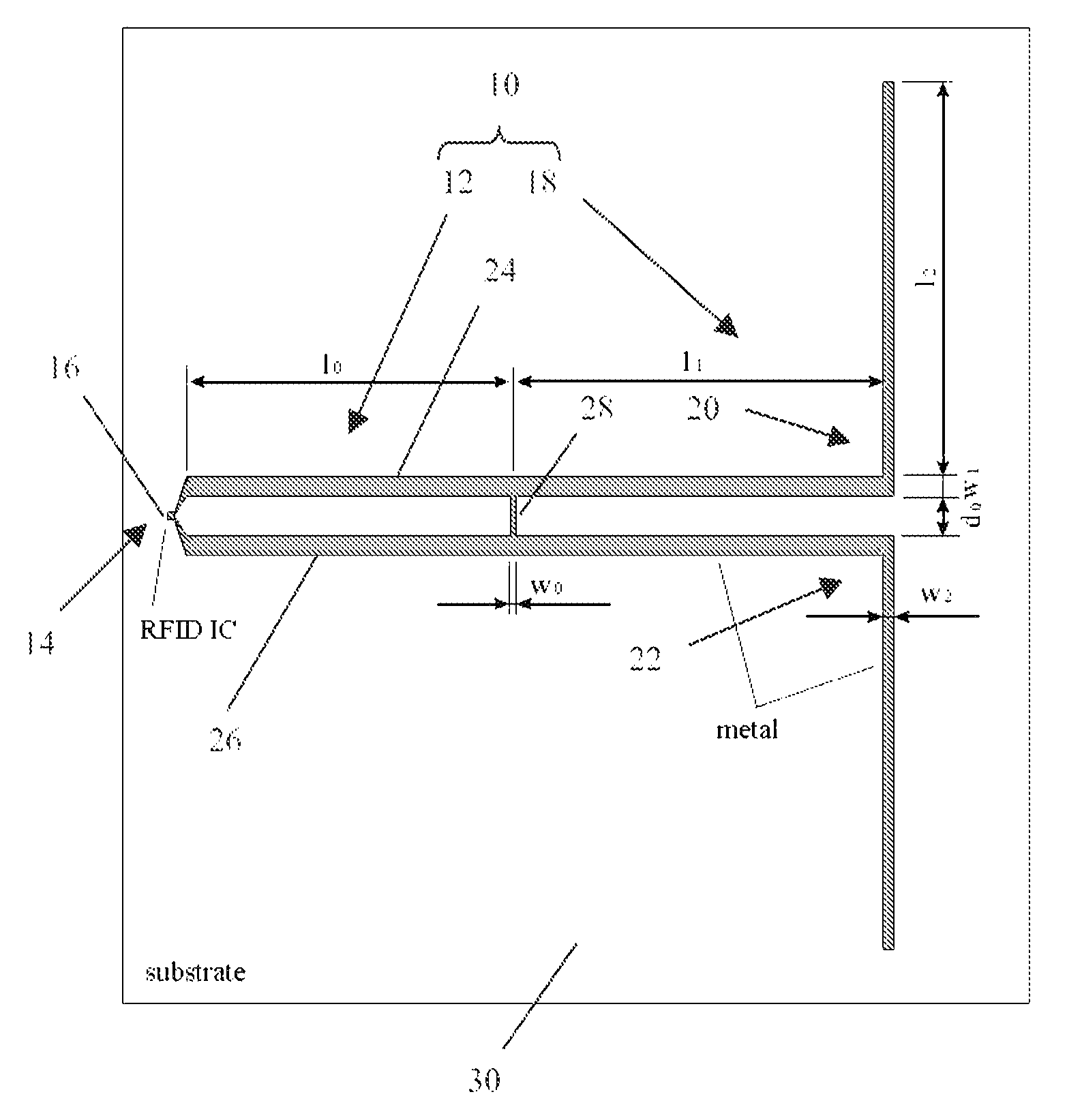
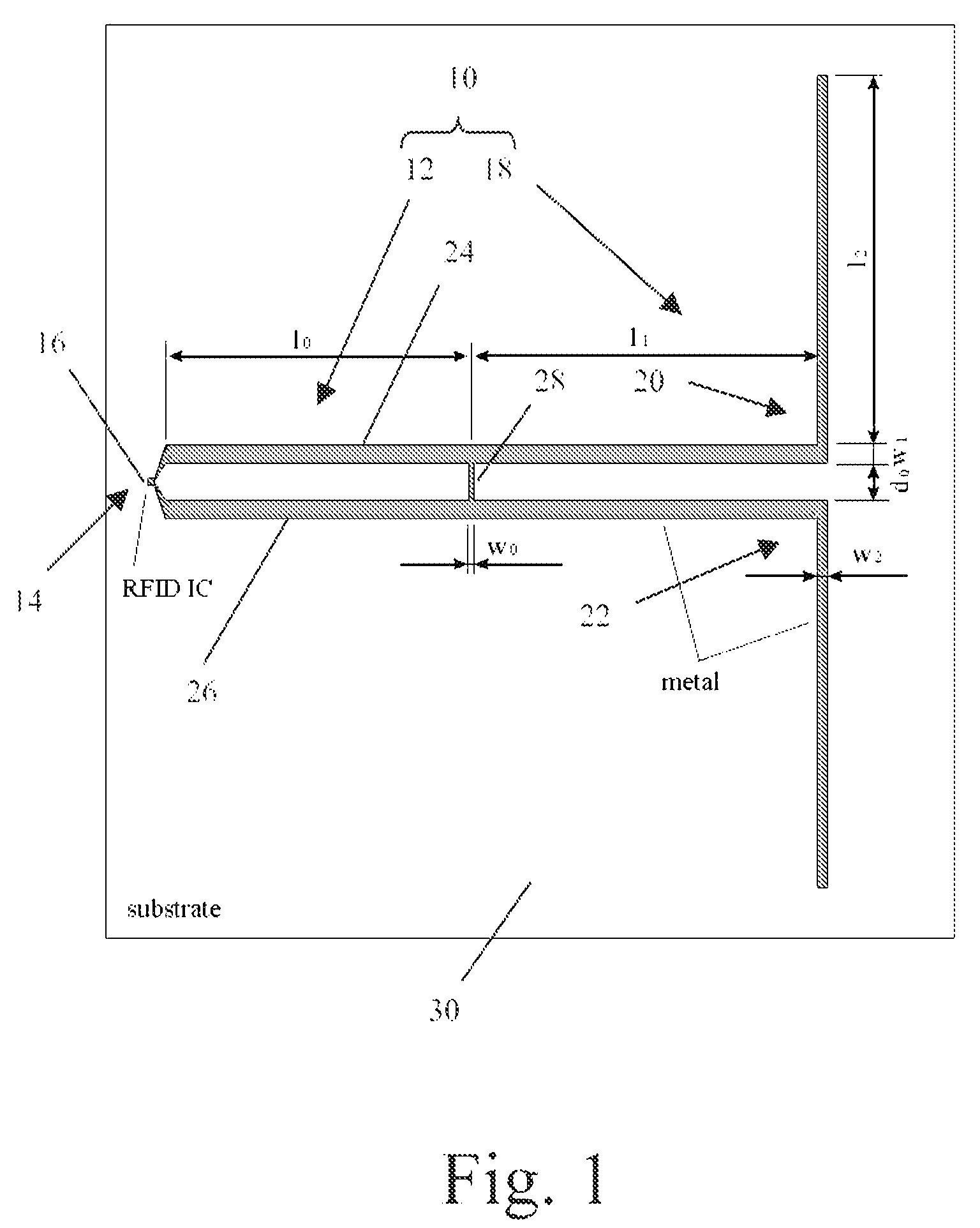
[0037]FIG. 1 shows an electrically isolating substrate 30 onto which an antenna 10 and a RFID integrated circuit 16 is mounted. The substrate 30 may be made of plastic, ceramic, plastic with embedded ceramic particles, etc., and has a dielectric constant ∈r equal or larger than 1 and a permeability coefficient μr equal or larger than 1. The antenna 10 may be implemented as an electrically conductive metallization, for example Cu, Au, Ag, Al, etc. deposited on or embedded into the substrate 30. The metallization may be structured by known methods such as etching, milling, printing, imprinting, or pasting and deposited on the substrate 30. The RFID transponder is formed by the antenna 10 and the RFID IC 16 connected to a so-called feedpoint 14 of the antenna 10. In fact the feedpoint 14 is realized by means of two tiny connection legs or w...


PUM


Abstract

A broadband antenna structure (10) for a transponder of a radio frequency identification system comprises —a loop resonator (12) with a feedpoint (14) for connecting with an electronic circuit (16), and —a dipole resonator (18) electrically connected to the loop resonator (12) and comprising two electrically isolated legs (20, 22).

Description

FIELD OF THE INVENTION[0001]The invention relates to a broadband antenna for a transponder of a radio frequency identification system.[0002]The invention further relates to a transponder of a radio frequency identification system.BACKGROUND OF THE INVENTION[0003]Radio frequency identification (RFID) systems typically comprise one or more reader powered by a battery or power supply unit and capable of communicating with RFID transponder or tags. A RFID transponder may be an active tag which is powered by a battery, or a passive tag which is powered by the high frequency field generated by the reader, or a semi active / passive tag which is activated by the high frequency field generated by the reader and uses a battery for further activities. It comprises at least electronic circuitry for storing data and communicating with a reader, and an antenna tuned with the frequency range in which the RFID transponder is operated.[0004]Usually, different frequency ranges are provided for contact...

Claims


Application Information

Patent Timeline
Patent Type & Authority Applications(United States)
IPC IPC(8): H01Q21/00H01Q9/16H01Q7/00H01Q5/00H01Q5/357H01Q5/371
CPCH01Q1/2225H01Q1/38H01Q5/00H01Q7/00H01Q5/371H01Q9/28H01Q21/30H01Q5/357H01Q9/16
Inventor HILGERS, ACHIM
Owner NXP BV
Why Eureka
Try Eureka